
Tus neeg siv phau ntawv

- 44 -
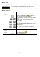
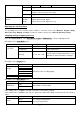
Bus Trigger
1. SPI
Trigger on specified data when timeout conditions are met. When using the SPI trigger, SCL and SDA data
must be specified.
In SPI trigger mode, the setting information is displayed at the bottom right of the screen, e.g.:
indicates that the trigger is in SPI mode, CH1 as trigger level is 0.00mV
and CH2 as trigger level is 0.00mV.
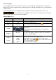
Menu
Setting
Description
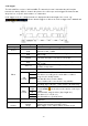
Bus Type
SPI
Set vertical bus type as SPI triggering
Source
CH1
CH2
Set CH1 as SCL or SDA
Set CH2 as SCL or SDA
Timeout
Time out
Set the minimum time that SCL must be inactive. A range
of 100ns~10s is available before the oscilloscope starts
searching for the measurement data (SDA) to be triggered.
Use the Multi ( ) knob or the touch control to set.
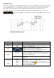
ClockEdge &
Data
Clock Edge
Set Clock Edge as a rising or falling edge. Thus, the SDA
data is sampled on the rising or falling edge.
Data Bits
Set the number of the serial data bit string. This value can
be set between 4 and 32. Use the Multi ( ) rotary knob or
the touch control.
Current Bits
Set the number of the data bits from 0-31.
Data
Use the Multi ( ) knob or touch control to set the Current
Data Bit value as H, L or X(H or L).
All Bits
Set all data bits as specified values.
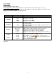
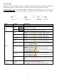
Fashion
Holdoff
Car
Normal
Single
Capture waveform even if no trigger occurs
Capture waveform when a trigger occurs.
When trigger occurs capture a wave and then stop it