
Tus neeg siv phau ntawv

- 41 -
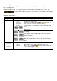
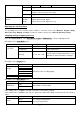
7. timeout trigger
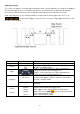
The unit triggers when the time interval (from when the rising edge (or falling edge) passes through the
trigger level to when the adjacent rising or falling edge passes through the trigger level) is greater than the
set timeout time.
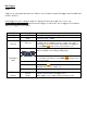
In timeout trigger mode, the setting information is displayed at the bottom right of the screen, e.g.:
indicates that the timeout trigger on CH1 has been selected with positive polarity
and the up-level and low-level threshold is 0.00mV.
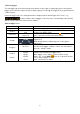
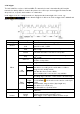
Timeout trigger menu:
Menu
Setting
Description
Trigger mode
Timeout
Set vertical trigger type as timeout triggering
Source
CH1
CH2
Channel 1 as trigger signal.
Channel 2 as trigger signal.
Threshold
Up Level
Low Level
Select the level setting with the Multi ( ) rotary knob or
tap +/- via touch screen for threshold setting
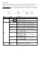
Polarity
Polarity
Starts timing when the rising edge passes through the
trigger level.
Starts timing when the falling edge passes through the
trigger level.
Configure
Idle Time
Sets the idle time. This means the minimum time of an idle
time before the trigger conditions can be met. Selectable is
30ns-10s, default is 100ns.
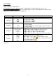
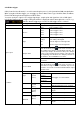
Fashion
Holdoff
Car
Normal
Single
Holdoff
Reset
Capture waveform even if no trigger occurs
Capture waveform when a trigger occurs.
When trigger occurs capture a wave and then stop it
100ns~10s, use the Multi ( ) knob to set the time interval
before another trigger occurs.
Set the holdoff time as 100ns.