
User's Manual
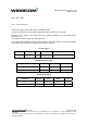
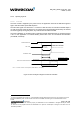
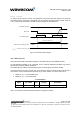
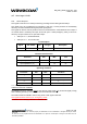
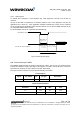
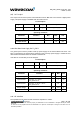

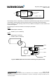
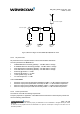
Table Of Contents
- General description
- Interfaces
- General Purpose Connector (GPC)
- Power supply
- Electrical information for digital I/O
- LCD interface
- SPI Auxiliary bus
- Keyboard interface
- Main serial link (UART1)
- Auxiliary serial link (UART2)
- SIM interface
- General Purpose Input/Output
- Activity status indication
- Analog to Digital Converter (ADC)
- Audio interface
- Battery charging interface
- ON / ~OFF
- BOOT (optional)
- Reset signal (~RST)
- External Interrupt (~INTR)
- VCC output
- Real Time Clock Supply (VCC_RTC)
- RF interface
- Technical specifications
- Appendix

WM_PRJ_Q2400_PTS_002 - 004
March 5, 2004
2.17 Reset signal (~RST)
2.17.1 General description
This signal is used to force a reset procedure by providing low level during at least 500 µs.
This signal has to be considered as an emergency reset only. A reset procedure is automatically
driven by an internal hardware during the power-up sequence.
This signal can also be used to provide a reset to an external device. It then behaves as an output. If
no external reset is necessary this input can be left open. If used (emergency reset), it has to be
driven by an open collector or an open drain output:
• ∼RST pin 14 = 0, for Module Reset,
• ∼RST pin 14 = 1, for normal mode.
Pin description
Signal Pin number I/O I/O type Description
∼RST
14 I/O SCHMITT Module Reset
Electrical Characteristics
Parameter Min Max Unit
Input Impedance ( R ) 4.7
kΩ
Input Impedance ( C ) 10 nF
Operating conditions
Parameter Min Max Condition
*V
T-
1.1 V 1.2 V
*V
T+
1.7 V 1.9 V
V
OL
0.4 V I
OL
= -50 µA
V
OH
2.0 V I
OH
= 50 µA
* V
T-,
V
T+ :
Hysteresis thresholds
Additional comments on RESET:
The RESET process is activated either
by the external ~RST signal or by an internal signal (coming
from a RESET generator). This automatic reset is activated at Power-up.
The module remains in RESET mode as long as the ~RST signal is held low.
This signal should be used only for “emergency” resets
.
A software reset is always preferred to a hardware reset.
confidential ©
Page : 35 / 63
This document is the sole and exclusive property of WAVECOM. Not to be distributed or divulged without prior written
agreement.
Ce document est la propriété exclusive de WAVECOM. Il ne peut être communiqué ou divulgué à des tiers sans son
autorisation préalable.