
User's Manual
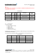
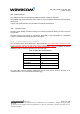
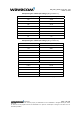
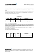
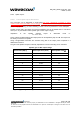
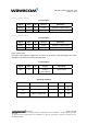
Table Of Contents
- General description
- Interfaces
- General Purpose Connector (GPC)
- Power supply
- Electrical information for digital I/O
- LCD interface
- SPI Auxiliary bus
- Keyboard interface
- Main serial link (UART1)
- Auxiliary serial link (UART2)
- SIM interface
- General Purpose Input/Output
- Activity status indication
- Analog to Digital Converter (ADC)
- Audio interface
- Battery charging interface
- ON / ~OFF
- BOOT (optional)
- Reset signal (~RST)
- External Interrupt (~INTR)
- VCC output
- Real Time Clock Supply (VCC_RTC)
- RF interface
- Technical specifications
- Appendix

WM_PRJ_Q2400_PTS_002 - 004
March 5, 2004
Electrical Characteristics
Parameter Conditions Min Typ Max Unit
SIM_DATA V
IH
I
IH
= ± 20 µA
0.7xSIM_VCC V
SIM_DATA V
IL
I
IL
= 1 mA
0.3xSIM_VCC V
SIM_RST,
SIM_DATA
SIM_CLK V
OH
Source current =
20 µA
SIM_VCC – 0.1V V
SIM_RST,
SIM_DATA
SIM_CLK V
OL
Sink current =
-200 µA
0.1 V
SIM_VCC* Output
Voltage
I
SIMVCC
<= 6 mA
2.70 2.80 2.85 V
SIM_CLK
Rise/Fall Time
Loaded with 30 pF
50 ns
SIM_RST,
SIM_DATA
Rise/Fall Time
Loaded with 30 pF
1 µs
SIM_CLK
Frequency
Loaded with 30 pF
3.25 MHz
(*): given for a 3 V interface. An external SIM driver is needed to handle 5 V SIMs.
Note for SIM_PRES connection
:
• When not used SIM_PRES has to be tied to VCC.
• When used, a low to high transition means that the SIM card is inserted and a high to low
transition means that the SIM card is removed.
2.9.2 SIM 3/5V management
The WISMO Quik Q24x6 sub-series module is designed to interface with 3 V SIMs only
1
.
Nevertheless, it is possible to manage 3 V and 5 V SIM cards using an external level shifter (refer to
customer design guidelines [1]). In this case, depending on the type of SIM detected, the module
firmware triggers the GPO0 output signal (pin #26) in order to properly set the external SIM driver
level (3V or 5V).
confidential ©
Page : 22 / 63
This document is the sole and exclusive property of WAVECOM. Not to be distributed or divulged without prior written
agreement.
Ce document est la propriété exclusive de WAVECOM. Il ne peut être communiqué ou divulgué à des tiers sans son
autorisation préalable.
1
Most of the GSM operators have been providing 3 V SIMs since 1998.