
User's Manual

WWW.NBSTECH.COM
8
Before installing this equipment, users should ensure that it is
permissible to be connected to the facilities of the local tele-
communications company. The equipment must also be in-
stalled using an acceptable method of connection. The cus-
tomer should be aware that compliance with the above condi-
tions may not prevent degradation of service in some situa-
tions.
Repairs to certified equipment should be coordinated by a rep-
resentative designated by the supplier. Any repairs or altera-
tions made by the user to this equipment, or equipment mal-
functions may give the telecommunications company cause to
request the user to disconnect the equipment.
Users should ensure for their own protection that the electrical
ground connections of the power utility, telephone lines, and
internal metallic water pipe system, if present, are connected
together. The precaution may be particularly important in rural
areas.
Caution: Users should not attempt to make such connections
themselves, but should contact the appropriate electric inspec-
tion authority, or electrician, as appropriate.
IC RSS-102 (SAR) Compliance
This POS terminal has been evaluated and found to comply
with the RF exposure limits for humans, as specified in Health
Canada’s Safety Code 6, when used with the NBS Technolo-
gies Inc. accessories supplied or designated for this product
and when the position of the terminal is a minimum of .4” (10
mm) from the body. Use of other accessories may not ensure
compliance with IC/FCC RF exposure guidelines.
Standards
USA
FCC Part 15: Radio Frequency Devices
FCC Part 68: Connection of the terminal equipment to the tele-
phone network
FCC Part 22: Public Mobile Services
FCC Part 24: Personal Communication Services
NBS5500
INSTALLATION & OPERATION MANUAL
21
PORTABLE CONNECTIONS
Travel BA–USB adapter is a NBS5500 accessory
(See “Accessories”).
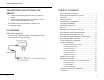
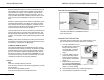
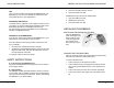
CONNECTING THE BATTERY
The battery pack is located in the unit, under the battery cover
flap. On a new device, the battery pack is not connected.
1. Turn the PORTABLE over on
the table with the bottom side
facing up and remove the
cover flap (See " Opening/
Closing the Battery Cover
Flap.")
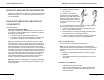
2. Locate the battery pack con-
nector foolproofing and the
board connector located un-
der the battery compartment
(Figure 1).
3. Plug the battery pack connec-
tor on the board according to
the connector locating system and the wire colors
(Figure 1). Feel the locking.
4. Place the battery pack in its compartment (Figure 2).
5. Close the battery compartment cover flap.