
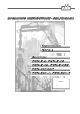
User Manual

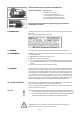

Steady light of the green LED : The battery charger is ready for use.
Place the battery in the charger.
If the battery is totally discharged, the yellow LED flashes slowly during pre-charging.
Steady light of the yellow LED: The battery will now be charged.
The yellow LED flashes quickly: The charging process is finished.
No harm will come to the battery if it is left in the charger beyond the required char-
ging time.
Optional: Integrated battery charger if DC-supply: In the receivers PNN-R-6 and PNN-R-
10. In PNN-R-16, -CAN and PNN-Compact rapid charging in about 1 hour. In PNN-BUS-
3about3hours. Use this battery charger only in closed rooms.
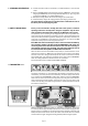
The receiver is connected to the unit to be controlled with the multi-pin connecting
cable supplied. Please observe the instructions issued by the manufacturer of the unit
to be controlled!
The power supply of the receiver is generally effected by the connecting cable.
(if existing)
Do not use the charger other than in dry rooms having a min-max tempera-
ture range of 0-40°C! A charged battery is a concentrated energy source.
Never store a charged battery in a toolbox or similar where it could be short-
circuited by metal components (even a key in your trouser pocket can cause
ashortcircuit).
We recommend urgently to realize this connection via a cen-
tral, well accessible, multi-pin plug connector (for example HTS-plug connec-
tor series HE/HB/HN/HA or comparable ones of other manufacturers) to
make possible a quick and clear fault diagnosis in the service case and to
take off the receiver without an expenditure of assembly.
In general, an earth lead is required in case the units to be controlled
have not previously been operated by radio control. Failing this, the
receiver electronic circuit will not receive any power supply. Ensure that
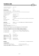
the operating voltage of the receiver complies with the electrical specifi-
cations of the unit to be controlled. The applicable operating voltage is
specified in the supplement.
Never expose the receiver to a high pressure cleaning jet. This applies to
the transmitter also.
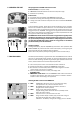
The receiver should always be fixed vertically at the outside panel of the
switching cabinet. (The antenna should always reach over the top of the
panel.)
You have to make sure that the an tenna is not shielded by metal parts
totally or partly.
Mounting the receiver in a cabine or in a switching cabinet the antenna
should be layed with an extension cable to the outside and be attached with
the fastening strapping as horizontally as possible with distance to the
shielding metal parts.
In general the antenna should always be mounted in such a way so that the
antenna is still visible with each change of position of the transmitter.
%
%
%
%
%
%
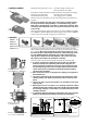
PNN-Compact PNN-BUS-3 PNN-BUS-5PNN-R-6, -16, -CAN PNN-R-10
5. RECEIVER
PNN-R-6, -10
PNN-R-16
PNN-R-CAN
PNN-Compact
PNN-BUS-3, -5
Page 2
Mounting possibility
of the PNN-BUS-3 or PNN-BUS-5.
Mounting possibility
of the PNN-Compact
Mounting possibility of the PNN-R-6,
-10, -16 oder des PNN-R-CAN.
WRONG
WRONG
RIGHT
Mounting on a tower slewing crane.
Top sl ewing crane: Mount t he antenna wit h
extension cable horizontally.
RIGHT
4. BATTERY CHARGER