RADIO CONTROL SYSTEMS Operating instructions Nano-M SMJ USA/Canada Compact-M Transmitter Type / Factory No. Frequency Receiver Type / Version Factory No. Frequency Version OTTO-HAHN-STR. 3 - 5 DE-75248 ÖLBRONN-DÜRRN TEL.: +49(0)7237/ 999-0 FAX: +49(0)7237/ 999-199 E-MAIL: sales@nbb.de INTERNET: www.nbb.
Table of contents General information 2 Transmitter Nano-M SMJ 4 Receiver Compact-M 10 Accessories 13 Technical documents 17 1
General information Standard scope of delivery n Transmitter including carrying system n Receiver with integrated mounting holes n Connection cable for the receiver The order confirmation and/or the delivery note when the system is received is binding for the actual scope of delivery. Safety information Even if you have already operated radio control systems, always read these operating instructions before commissioning.
Maintenance Your NBB radio control system is maintenance-free to a large extent. Nevertheless observe the following points: n Regularly check the EMERGENCY STOP and STOP function. n Remove remnants of building material. n Disconnect receiver from the power supply for arc welding work, otherwise there is a risk of damage to the receiver electronics. n Regularly check wear parts.
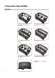
Transmitter Nano-M SMJ Variations Nano-M SMJ with a display and 2 joysticks Nano-M SMJ with 3 joysticks Nano-M SMJ with a display and 8 joysticks Nano-M SMJ with 6 joysticks Nano-M SMJ with a display and 3 joysticks Nano-M SMJ with 4 joysticks Nano-M SMJ 7.
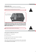
Commissioning Operating voltage 7.2 V: Insert the battery in the battery compartment for commissioning. For removal, press in the locking pin to unlock and slide out the battery to the side. Completely charge the rechargeable battery before initial use. Press in the locking pin and slide out the battery If the NBB radio control system is not to be used for a long time, it is strongly recommended to charge the battery approx. every 4 weeks.
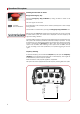
Operation of the system Switching the transmitter on and off Design with emergency stop Unlock the Emergency Stop pushbutton by turning clockwise to switch on the transmitter. Two short signals can be heard. Operation: The red dot flashes. A red dot flashes in the LED display and an antenna symbol appears in the LC display during operation. The transmitter is switched off by pressing the Emergency Stop pushbutton once.
Operation of the system Channel number: During operation, the set channel can be displayed by pressing the «Frequency switching» key. Please refer to the technical annex for the exact position of the «On/Horn» and «Frequency switching» keys. Battery life warnings: The LED display of the active battery flashes green during operation. When the control lamp flashes orange, the battery indicates a remaining capacity of approx. 10%.
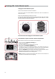
Technology SMJ - Surface Mounted Joystick Changing the Surface Mounted Joystick: Switch off the transmitter and remove the batteries. Loosen all 4 screws of the Surface Mounted Joystick with a Torx 10 screwdriver and remove the screws. Remove the Surface Mounted Joystick from the top. Insert the new Surface Mounted Joystick and make sure that the plugs and sockets are above each other. Screw down the Surface Mounted Joystick with the 4 screws previously removed and reinsert the batteries.
Technology SMJ - Surface Mounted Joystick 1 Surface Mounted Joystick teach mode activation with pushbutton and display: n To activate teach mode, the transmitter must be switched off. 1. Press and hold the «Frequency switching» key. 2. Switch the transmitter on. 3. «Joy Teach» with graphics appears in the display after 2 seconds. Now release the «Frequency switching» key. 5. Completely move the Surface Mounted Joystick in one direction and return it to the 0-position. Repeat this for all directions.
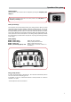
Receiver Compact-M Variations 10 Compact-MA Compact-MB Compact-MC Compact-MD
Commissioning The receiver is connected via a connection cable to the system to be controlled. Please observe the instructions of the system manufacturer when installing. We strongly recommend establishing this connection via a central, easily accessible plug connection (e.g. Tyco type (HTS) plug connection, series HE/ HB/HN/ HA, or a comparable one from a different manufacturer) to enable a fast and precise error diagnosis for servicing and to be able to remove the receiver without installation work.
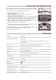
Function control Meaning of the LED display on the Compact-M: LED RADIO ON SERVICE CONNECTOR Receiver connect to power, without communication with transmitter: 1. LED constant ON (green) 2. LED flashing irregular (orange) -> receiver searching transmitter Connect to transmitter: 1. LED flashing regular (green) 2. LED flashing regular (orange) -> communication ok 1. LED flashing irregular (green) 2. LED flashing irregular (orange) -> Interference on RF signal -> (change frequency) 1.
Accessories Battery - 7.2 V Completely charge the battery before initial use. Never put an uncharged battery into operation as it can be destroyed as a result. Only completely discharged batteries should be charged. Always remember to operate your controller until the capacity of the battery is completely depleted.The battery only has its maximum capacity after five complete charging and discharging procedures! Completely discharge the battery in the control unit before charging again.
Technical data Technology NiMH Voltage 7.2 V Capacity 1500 mAh Maximum charging current 1,0 C (with appropriate monitoring) Operating temperature (discharge) From -20 to +60 °C Operating temperature (charge) From +10 to +35 °C Measurements (L x W x H) Approx. 126 x 52 x 22 mm Weight Approx.
Charger for NiMH rechargeable batteries (7.2 V) Instructions for use Display of the charging procedure via a DUO-LED: LED - continuously lights up green: STANDBY. Charger is ready for operation. Insert the battery in the battery compartment. LED - continuously lights up orange: CHARGING. The battery is being charged. Charging complete. LED - rapidly flashing orange: LED - slowly flashing orange: Battery is deeply discharged or ambient temperature for quick charging is too low.
Charger for NiMH rechargeable batteries (7.2 V) Mounting instruction Please refer to the drawing for the measurements for attachment. mm Technical data Power supply by 12 V / 24 V on-board electrical system or external power supply Supply voltage 9 V - 32 V DC (Note: the charging procedure is lengthened below 10V) Power supply system Via coaxial power connector (external = 5.5 mm, internal = 2.1 mm) Measurements (L x W x H) 173.5 x 73 x 43.
US-FCC and CANADA IC USA: NOTE: This equipment has been tested and found to comply with the limits for a Class A digital device, pursuant to Part 15 of the FCC Rules. These limits are designed to provide reasonable protection against harmful interference when the equipment is operated in a commercial environment.
Technical documents 17
Approvals and certificates Approvals for EU countries: x Annex: EC Declarations of Conformity Available on request: M-Zert GmbH Certificate DIN EN ISO 9001:2008 Nº 03022 © NBB Controls + Components GmbH Otto-Hahn-Straße 3-5 DE-75248 Ölbronn-Dürrn Tel.: 0 72 37 / 9 99 - 0 Fax: 0 72 37 / 9 99 - 1 99 eMail: sales @nbb.de http://www.nbb.de We reserve the right to make technical and design changes. Operating instructions Nano-M SMJ, Compact-M Englisch, Teile-Nr. 3.150.1360, Stand 05.