C H A TRACKER950 R T P L O T T E R Installation and Operation Manual w w w. n a v m a n . c o m English...............4 Français...........
Contents 1 Introduction .................................................................................................... 6 1-1 Care ....................................................................................................................... 6 1-2 C-MAP™ chart cartridges ..................................................................................... 7 1-3 Removing and replacing the unit ........................................................................... 7 1-4 Navigation data ....
7 Fuel screen ................................................................................................... 26 8 Position screen ............................................................................................ 27 9 Menu screen ................................................................................................. 28 9-1 9-2 9-3 9-4 9-5 9-6 9-7 General Setup ..................................................................................................... 30 Navigation Setup .
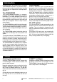
1 Introduction Congratulations on choosing the NAVMAN TRACKER950 chartplotter. For maximum benefit, please read this manual carefully before installing and using the unit. Special terms are explained in Appendix C. The TRACKER950 The TRACKER950 chartplotter is a compact, ruggedly built, highly integrated navigation instrument. It has been designed to be easy to use. Complex navigation functions can be performed with a few key presses, taking the hard work out of navigation.
1-2 C-MAP™ chart cartridges A C-MAP™ electronic chart cartridge has chart details required for navigating in a particular region. When you plug the cartridge in, the extra details are automatically superimposed on the TRACKER950’s built-in chart of the world. The cartridge plugs into a slot in the upper, left side of the display unit. When you insert or remove a cartridge it does not matter if the TRACKER950 is turned on or off. To insert a cartridge 1 Remove the protective cover from the C-MAP™ slot.
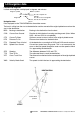
1-4 Navigation data Latitude and longitude Latitude and longitude are displayed in degrees and minutes: Degrees symbol Minutes symbol 43° 12.538' N Degrees N or S of equator for latitude E or W of zero for longitude Minutes, 0 to 60, to 3 decimal places Navigation data Data displayed on the TRACKER950 has three-letter names. The boat is sailing from the start to the destination and has moved off the original plotted course from the start to the destination.
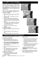
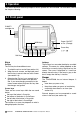
2 Operation This section describes the basic principles of how to operate the TRACKER950. For more detail, refer to the chapters following. 2-1 Front panel C-MAP™ cartridge slot Power ON/OFF or Esc (Escape) MOB Keys Cursor Key Soft Keys Keys Esc key The Esc key has three different uses: 1 To switch the unit on and off (see section 2-4). 2 When the main screens are displayed, press the Esc key to move to the next main screen (see section 2-6).
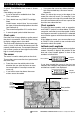
2-2 Chart displays A typical TRACKER950 chart screen is shown below. Chart displays can show: A part of the built-in worldwide chart. See Chart scale below Chart details from any C-MAP™ cartridge fitted. Land is brown, water is blue. You can control the type of information displayed on the chart (see section 9-4). The current boat position if it is on the chart. A cross-shaped symbol called the cursor. Chart scale Press the Zoom In key to display a smaller area of the chart in more detail.
2-3 Alarms When the TRACKER950 detects a condition outside the alarm parameters, it gives an alarm. It beeps continually and displays a warning message in a window. The following alarms can be enabled or disabled: Arrival Radius, Anchor Alarm, XTE Alarm and Low Fuel (see section 9-3). To clear the alarm, press the Esc key.
2-6 Main screens After you have turned the unit on (see section 24), it displays the Satellite Status screen until it acquires a position fix, then displays the Underway screen. This is one of the five main screens. Each main screen displays a particular navigation function.
2-7 Navigating The TRACKER950 has two ways of navigating, going straight to a point or following a route. the route by using the Waypoints screen (see section 6-1). Waypoints To create a route, go to the Routes screen (see section 6-2). You can create waypoints as you create the route. Before you start navigating, you can enter waypoints at points of interest (see section 6-1). Tip: create a waypoint at your marina so that you can navigate back easily.
3 Satellite Status screen The satellite status screen displays the signal strengths of the visible GPS satellites, their current positions and information about the accuracy of the calculated position. 3-1 GPS and DGPS worldwide navigation GPS and DGPS The US Government operates the GPS system. There are twenty-four satellites orbiting the earth that broadcast position and time signals. The positions of these satellites are constantly changing.
3-2 The Satellite Status screen When you turn the TRACKER950 on, the Satellite Status screen is automatically displayed while the GPS receiver starts up. To display this screen at any other time: press the Sat key in the Position or Fuel screen or choose it from the Menu screen The satellite status screen displays information about the GPS satellites: The current type of GPS fix, for example Acquiring, GPS fix, DGPS fix, No GPS. If the unit is in Simulation mode it displays Simulate (see section 2-8).
3-3 Mapshift screen and datums Satellite derived positions are based on a worldwide reference (datum) known as WGS84. Some paper charts are based on datums other than WGS84. This results in an offset between a latitude and longitude plotted on the paper chart and the same latitude and longitude plotted on the TRACKER950. To match the TRACKER950 with your local charts you must enter the datum for your local area (see Appendix A for a list of available datums).
4 Underway screen The Underway screen is the main screen for displaying your current location and heading while navigating. It displays: The chart with the boat position and track. Two user-definable data fields (see section 92).
4-1 GoTo screen GoTo is a simple way of navigating straight to one place: to the cursor position or to a waypoint. To cancel a GoTo 1 In the Underway screen, press the GoTo key. To start the GoTo 2 Press Cancel. The TRACKER950 will stop navigating to the destination. 1 In the Underway screen, zoom in or out until the boat and destination are visible. 2 Press the GoTo key. A dotted line joins the boat and cursor positions, showing the planned course.
5 Highway Screen The Highway screen displays a chart with your current position and heading when you are navigating to a destination: The destination is automatically positioned directly ahead, at the top centre of the chart. The boat position is automatically maintained in the centre of the chart. You can see on the chart where you are, where you are heading, and if you are approaching land or any dangerous water. It displays two vertical parallel lines, called the CDI (Course Deviation Indicator).
6 Navigation screen Use the Navigation screen to create edit and delete waypoints and routes. You can also calculate distances and bearings along a path on the chart. Esc key if fuel is enabled, go to the Fuel screen otherwise, go to the Position screen Waypts key Go to the Waypoints screen to add, change or delete waypoints (see section 6-1). Routes key Go to the Routes screen to add, change or delete routes (see section 6-2).
6-1-3 Create a new waypoint at the cursor or boat position 1 To edit the waypoint data: 1 Press the CursorUp or CursorDown keys to highlight the piece of data to change. 2 Press the Edit key to highlight a character in the piece of data. 3 To change the data, press the CursorLeft or CursorRight keys to highlight the character to change, then press the CursorUp or CursorDown keys to change the character.
Use the cursor keys to highlight a particular waypoint. These softkeys keys are available: Edit: Edit the data for the highlighted Waypoint (see section 6-1-6). Delete: Delete the highlighted Waypoint. You can not delete a waypoint if it is part of a route or the boat is going to the waypoint. Create: Create a new waypoint (see section 6-1-4). View: Display the chart with the waypoint in the centre of the screen. GoTo: Start the boat going to the waypoint (see section 4-1).
6-2 Routes List: Display a list of the routes, see section 6-2-5). 6-2-1 Introduction to routes A route is a list of waypoints that the boat can navigate along. Routes can be created, changed and deleted. A route can have between two and fifty waypoints. A route can start and stop at the same waypoint; in this case there must be three or more waypoints in the route. The boat can start at any waypoint in the route and can travel along a route in either direction. Waypoints on the route can be skipped.
where the new waypoint should be, then press the Add key. Edit the waypoint data as described in section 6-1-6. Press the Save key. cursor keys to change the name, then press the Enter key. 6-2-5 List the routes In the Routes screen, press the List key to display a list of all the routes. Cursor is not on the route The softkeys are: Use the cursor keys to highlight a particular route. The softkeys keys are: Start: Start the route (see section 6-2-7).
6-3 Distance and bearing calculator The Distance screen allows you to calculate the distance and bearings over a path on the chart. To display the screen: 1 Press the Esc key until the Navigation screen is displayed. 2 Zoom in or out so that the area of interest is displayed. 3 Press the Dist key. To calculate a distance and bearings over a path: 1 Move the cursor to the start of the path. Press the Start key. 2 Move the cursor to the next point on the path. Press the Next key.
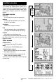
7 Fuel screen To use the fuel features, first purchase and install the optional single or twin engine fuel kit. If a fuel kit is installed but this fuel screen does not appear, you must enable it by setting Num Engines to 1 or 2 and setting up the other fuel data (see section 9-6). It displays: Used The total fuel used since it was last cleared. This can be reset to 0 by the Clear Used command (see section 9-6). Remaining The amount of fuel remaining in the fuel tank(s). Flow The fuel consumption.
8 Position screen This displays navigation data, with the latitude and longitude of the boat in large numbers. Esc key: Go to the Underway screen. Menu key: Go to the Menu screen. Highway key: Go to the Highway screen. Nav key: Go to the Navigation screen. Fuel key: Go to the Fuel screen. Sat key: Go to the Satellite status screen.
9 Menu screen The TRACKER950 has a number of advanced navigation features which are set up through this menu. We recommend that you become totally familiar with the operation of the unit using the default settings before making any changes to the data in these menus. To display the Menu, display the Position, Highway or Fuel screen and press the Menu key. Using the Menus A menu is a list of items.
Menu map, with default settings in brackets Menu Satellite Status screen General Setup Backlight (16) Local time Ofst (0) NMEA output (OFF) Language (English) Navigation Setup CDI/Units/Alarms Map datum (WGS84) North reference (Automag) Map orientation (North Up) Velocity averaging (20 secs) Projected course (OFF) User Data 1 (XTE) User Data 2 (TTG) User Data 3 (CDI Scale) User Data 4 (ETA) CDI scale (0.
9-1 General Setup Backlight NMEA Output Backlight brightness, 16 Levels Enable/Disable the NMEA0183 output for the autopilot or radar. Local Time Ofst The difference between local time and UTC (GMT). You must change Local Time Ofst when daylight saving time starts and ends. Language Select the language for the screens. The options are Dutch, English, French, German, Italian, Portuguese, Spanish and Swedish. 9-2 Navigation Setup Map Datum COG damping is also derived from this setting.
Anchor Alarm Low Fuel Alarm When the Anchor Alarm is enabled it gives an alarm when the boat moves by more than the Anchor Alarm distance. When the Low Fuel alarm is enabled it gives an alarm when the fuel remaining in the tank is less than the Low Fuel value. To enable the alarm, enter an Anchor Alarm distance (up to 9.99 distance units). The TRACKER950 saves the current boat position. To enable the alarm, enter a Low Fuel value. Ensure To disable the alarm, set the Low Fuel value to OFF.
9-5 Track History The Track History function plots the track of the boat on the chart. The TRACKER950 saves the boat’s position to memory at regular intervals, which can be: time intervals, from 1 second to 1 minute Up to 2000 positions can be stored and they are retained when the unit is turned off. This menu displays the amount of memory used to store the track. To delete the track, select Clear Track Memory. or distance intervals, from 0.01 to 10.
Flow Filter Sets the period over which the fuel flow is averaged. Averaging can be set from 1 to 180 seconds. Normally engines do not draw fuel from the tank at a steady rate. They draw fuel at a high rate for a few seconds until the carburettor bowl or fuel injection reservoir is full, then draw no fuel for a few seconds. If the true flow rate were displayed, it would be too erratic to read. satisfactory result for carburettor engines. Fuel injected engines may require a larger value.
10 Installation Correct installation is critical to the performance of the unit. There are two components to install, the TRACKER950 and a GPS or DGPS antenna. In addition, you can install an optional fuel kit in order to use the unit as a fuel computer.
10-3 Installation Do not cut the cable near a connector and do not try to disassemble a connector. Display unit 1 Keep the dust cover on the display unit during installation. Choose a location for the unit that is easily seen and is not exposed to the direct sun or water. To the left of the helm is preferred for when the helmsman is wearing polarised sunglasses. 2 Screw the mounting bracket to the boat with four screws.
GPS or DGPS 1 7 8 6 2 3 5 4 Fuel cable Pin Wire Signal 1 Black Ground / Fuel Transducer Fuel cable 1 3 5 7 8 Power/NMEA cable S 1 2 3 4 5 6 7 8 Fuel Transducer 2 - 3 White Ground Fuel Transducer 4 - 5 Red Do not connect 6 - Fuel Transducer 7 Yellow Differential Correction (IN) 8 Green Spare Fuel Transducer Power/NMEA cable Pin Wire Signal S Black Connect with 1 (Ground) 1 Black Ground, Power negative 2 Brown +13.
Appendix A - Specifications General Waypoints 500, with default or user-defined alphanumeric names Routes 25 reversible routes, with up to 50 points each Plotter log Plots by time or distance, saves up to 2000 points Alarms Arrival Radius, Anchor Alarm, XTE Alarm, Low Fuel (optional); individually controlled Chart datums 128 chart datums One user-defined map shift Chart cartridges C-MAP™ NT-Cards (16Mbit memory, 48Mbit max) Plotting scales 1/8 nm to 4096 nm with push-button zoom (chart dependent) Operation
Appendix B - Troubleshooting This troubleshooting guide assumes that you have read and understood this manual. 10 m for about 5 % of the time. b Under special circumstances the US Department of Defence may introduce a deliberate and changing error in the GPS positions of up to 300 m (1000 ft). This is called Selective Availability. The error is minimised if a DGPS antenna or differential receiver is installed. 8 TRACKER950 navigating in wrong region: In simulation mode.
d When refuelling, air pockets may have prevented the tank filling completely. e Recalibrate the fuel transducer after 100 litres have been used - so the turbine shaft has bedded into the bearings correctly. f Fuel transducers wear out over time and should be replaced every 5000 litres of fuel as a guide. 14 No or low fuel flow reading: a Check the fuel cable connectors are securely plugged in and the locking ring is locked in place. b Clogged fuel transducer.
Appendix C - Glossary The symbol for the boat on the display. The symbol for the cursor on the display. Attention Area: An important area on a C-MAP™ chart, such as a restricted anchorage or a shallow area (see section 9-4). BRG - Bearing to destination. Bearing to the destination from the boat. CDI - Course Deviation Indicator. On the Highway screen, a graphical indication of the distance from the boat to the original plotted course (XTE) (see section 5). COG - Course Over Ground.
Appendix D - Conditions of Sale & Warranty IMPORTANT: Some of the following terms and conditions vary from country to country. Please check with your NAVMAN dealer from whom you purchased your product. A. Conditions of Sale Except to the extent otherwise required by the laws of the country in which the accompanying product (“the product”) is sold the manufacturer of the product Talon Research & Development Co.
Appendix E - How to contact us More information is available on-line at our website www.navman.com Distributors: Argentina HERBY Marina S.A. Costanera UNO, 1425 Buenos Aires, Argentina Tel: (54) 11 4312 4545 Fax: (54) 11 4312 5258 e-mail: herbymarina@ciudad.com.ar Australia Talon Technology Australia PTY. Ltd. 2/340 Darling Street, Balmain NSW 2041, Australia Tel: (61) 2 9818 8382 Fax: (61) 2 9818 8386 Toll free fax 1300 303 105 e-mail: sales@navman.com.au China Peaceful Marine Electronics Co., Ltd.
Lon 174° 44.535`E TRACKER950 Made in New Zealand 1951060A MN000084 Lat 36° 48.404`S Designers and manufacturers of GPS, communication and marine products.