NAVMAN RESET MULTI NAVMAN
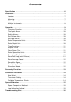
Contents Specification . . . . . . . . . . . . . . . . . . . . . . . . . . . . . . . . . . . . . . . . . . . . . . . . . . . . . . . . . 6 Installation . . . . . . . . . . . . . . . . . . . . . . . . . . . . . . . . . . . . . . . . . . . . . . . . . . . . . . . . . . . 7 Location . . . . . . . . . . . . . . . . . . . . . . . . . . . . . . . . . . . . . . . . . . . . . . . . . . . . . . . . . . 7 Mounting . . . . . . . . . . . . . . . . . . . . . . . . . . . . . . . . . . . . . . . . . . . . . . . . . . . .
Specification • Power Supply • Maximum speed 10.7 to 16.6 VDC, 90 mA nominal, 100 mA with backlights on full. • Operating temperature Records max. speed to 50 knots. Reset to zero via key pad or at power down. • Log (Trip distance) 0°C to 45°C. • Size of display 112 x 112 x 24mm (4.4 x 4.4 x 1”), overall depth 35mm (1.4”) behind panel. 0 to 99999 units key pad selectable in Kts, Mph or kph. Shows two decimal places when value is below 1000. Shows one decimal place if value is between 1000 and 10000.
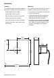
Installation Location Mounting The NAVMAN M100 is designed for above or below deck installation. Select a position that is: The mounting surface must be flat. Use the template to set the centre of the fixing hole. • At least 300mm from a compass • Drill a 32mm (1.25”) diameter mounting hole through the bulkhead.
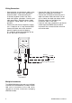
Wiring Connection • Keep electrical and transducer cables away from alternator or other noise generating electrical cables. Avoid connecting the instrument to power circuits that share loads with ignition, alternators, inverters and radio transmitters. Electrical power supply connections should always be as short as possible. • Connect the red wire to the positive supply via a 1 amp fuse or a 1 amp circuit breaker. Connect the black wire to the electrical ground (negative terminal of battery).
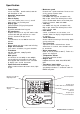
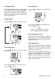
Operation Changing Functions The upper and lower display sections can be configured to display depth or speed readings. The remaining functions are available on either the upper or lower display only. The key selects functions available on the lower display. The selection remains in memory after power down. key selects functions available on the The upper display. The selection remains in memory after power down.
The Depth Alarms Set Deep Alarm The shallow water alarm sounds when the depth falls below the selected value. The deep water alarm sounds when the depth exceeds the selected value. When an alarm is activated the beeper will sound continuously and the bell alarm symbol will flash. Press the mode. and keys to enter deep alarm Setting Alarms Press the key to switch the alarm on or off. DEPTH Use the Press the and keys to set alarm value. key to exit.
Timer Functions Count Down Timer All timer functions are displayed on the lower section of the display. Press the key twice to show the count down timer. This timer counts down in seconds from a starting value that can be set in whole minutes from 1 to 10. Elapsed Timer The elapsed timer will record time from power up. Time is displayed in hours and minutes up to 99 hours and 59 minutes. Press the key to show elapsed time. When countdown timer mode is entered the last starting value used is displayed.
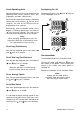
Select Speed/Log Units Backlighting On / Off Speed and distance units can be selected in the following order; Knots (nautical miles), kph (kilometres) and Mph (statute miles). Simultaneously press the turn the backlight on or off. When the top section of the display is indicating key for three speed, press and hold the seconds. The new unit of measure will be displayed for three seconds.
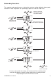
Secondary Functions The secondary modes provide access to keel offset, transducer setting, calibration of boat speed, calibration of water temperature and speed display options of 1/10th or 1/100th units.
Calibration Procedures Note: If the speed and depth readings flash, this indicates that the calibration values have been lost. To correct this, check the depth units, alarm values, keel offset, speed units and the speed calibration. To enter the transducer setting into memory and key. exit, press the Calibrate Temperature Display To adjust the temperature displayed. Keel Offset The NAVMAN M100 will normally display the depth of water below the face of the transducer.
Speed Calibration Speed Comparison Method Use the following sequence to adjust the speed displayed to match that of another craft or the speed displayed on a GPS receiver. Follow the Secondary Functions chart to reach Speed Calibration mode. Follow the Secondary Functions chart to reach Speed Calibration mode. to set the displayed speed to the Use the new value. For our example, assuming we started with the factory default calibration, this new speed would be 10.0 x 1.25 which is 12.5 knots.
Troubleshooting Chart No display: Check DC power connections and DC polarity with voltmeter. Voltage must be between 10.7 and 16.6 volts. No speed reading: 1. Remove speed impellor from skin fitting, spin paddlewheel manually and check for reading. 2. Check for fouling on paddle and skin fitting. 3. Check for break in cable. Low or high speed reading: 1. Check calibration. 2. Inspect for damage to paddlewheel or fouling of fitting or paddle. Erratic speed reading: 1.