
Installation Manual


Table Of Contents
4 - Hailer Horn
Wire color Function Details
White (+) Connect to hailer speaker +
Shield (-) Shield Connect to hailer speaker -
Important: Do not short these 2 wires. Install the hailer horn in a forward-facing location
on the boat because the hailer horn will transmit the FOG horn sounds and will ‘listen back’
when not transmitting.
Note: We recommend you use a hailer horn of 4 Ohms to obtain maximum 30 W audio
output power.
5 - External speaker
You can connect 1 x 2 W 8Ω or 1 x 4 W 4Ω speaker to the 3.5 mm speaker connector.
A speaker cable with 3.5 mm plug is provided to make the connection to the speaker.
Wire color Function Details
White Speaker (+) Connect this wire to the positive terminal of the speaker.
Black Speaker (-) Connect this wire to the negative terminal of the speaker.
6, 7 - DC Power
Wire color Function Details
6 - Red (+) 13.6 V DC Connect this wire to the positive battery terminal. Use at
least a 10 A fused 13.6 V DC electrical service to the radio.
7 - Black
(-) Ground
Connect this wire to the battery negative terminal.
8 - Ground
The vessels battery negative must be common to the boat’s Ground. (Optional) You can
connect the base station to the boat’s Ground. Use the Ground screw and Ground plain
washer supplied to make this connection.
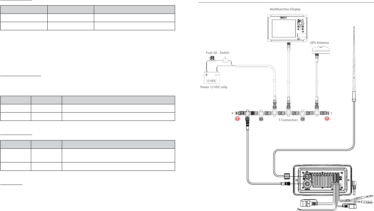
3.2 Wiring diagram - NMEA 2000 connections
NMEA 2000 Network
VHF Antenna
Link8 VHF
120
T
120
T
+
12 VDC
GPS Antenna
T-Connectors
Fuse 5A
Switch
Power 12 VDC only
Multifunction Display
MARK
MOB
GOTO
MENU
PAGES
STBY
IN
MOB
OUT
AUTO
SIMRAD
NSS 7
P
U
S
H
T
O
E
N
T
E
R
Simrad - RS35 Installation Instructions14 Simrad - RS35 Installation Instructions 15