
User's Manual
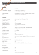
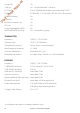
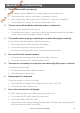
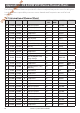
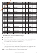
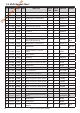
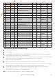
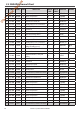
Table Of Contents
- Section 1 - General Information
- Section 2 - The Radio Menu (MENU)
- Section 3 - Radio Setup Menu (RADIO SETUP)
- Section 4 - DSC Setup Menu (DSC SETUP)
- 4-1 DSC Setup - Menu Options
- 4-2 Enter or View Your USER MMSI (USER MMSI)
- 4-3 Maintain Your Groups (GROUP SETUP)
- 4-4 Response to Individual Calls (INDIV REPLY)
- 4-5 ATIS MMSI & ATIS Functionality
- 4-6 DSC functionality options (DSC FUNC)
- 4-7 Response Type to LL Polling Calls (LL REPLY)
- 4-8 Automatic Channel switching (AUTO SWITCH)
- 4-9 DSC Test Reply (TEST REPLY)
- 4-10 Set the inactivity timer (TIMEOUT)
- 4-1 DSC Setup - Menu Options
- Section 5 - Sending and Receiving DSC Calls
- 5-1 What is DSC?
- 5-2 Sending DSC calls
- 5-2-1 Make a Routine Call (INDIVIDUAL)
- 5-2-2 Retrying a Routine Call
- 5-2-3 Acknowledgement of an Individual Incoming Call (INDIV)
- 5-2-4 Recall the Most Recent Incoming Call (LAST CALL)
- 5-2-5 Call a Group (GROUP)
- 5-2-6 Call All Ships (ALL SHIPS)
- 5-2-7 Call using the Call Log (CALL LOG)
- 5-2-8 Call using the Distress Log (DISTR LOG)
- 5-2-9 Call using the Sent Call Log (SENT CALL)
- 5-2-10 Request the LL Position of a Buddy (LL REQUEST)
- 5-2-11 Make a DSC test call (DSC TEST)
- 5-3 Receiving DSC Calls
- 5-2 Sending DSC calls
- 5-1 What is DSC?
- Section 6 - Distress Calls
- Section 7 - Installation
- Appendix A - Technical Specifications
- Appendix B - Troubleshooting
- Appendix C - US & ROW VHF Marine Channel Charts
- Appendix D - EU VHF Marine Channel Charts
- Appendix E - MMSI, FCC and License Information

Lowrance | Link-5 VHF User Guide 53
Appendix B - Troubleshooting
1. The transceiver will not power up.
A fuse may have blown OR there is no voltage getting to the transceiver.
a. Check the power cable for cuts, breaks, or squashed sections.
b. After checking the wiring, replace the 7 Amp fuse (1 spare fuse is supplied).
c. Check the battery voltage. This must be greater than 10.5 V.
2. The transceiver blows the fuse when the power is switched on.
The power wires may have been reversed.
a. Check that the red wire is connected to the positive battery terminal, and the black
wire is connected to the negative battery terminal.
3. The speaker makes popping or whining noises when the engine is running.
Electrical noise may be interfering with the transceiver.
a. Re-route the power cables away from the engine.
b. Add a noise suppressor to the power cable.
c. Use resistive spark plug wires and/or use an alternator whine filter.
4. No sound from the external speaker.
a. Check that the external speaker cable is physically connected.
b. Check the soldering of the external speaker cable.
5. Transmissions are always on low power, even when high (HI) power is selected.
The antenna may be faulty.
a. Test the transceiver with a different antenna.
b. Have the antenna checked out.
6. Battery symbol is displayed.
The power supply is too low or too high.
a. Check the battery voltage. This should be at least 10.5 V ± 0.5 V DC.
b. Check the alternator on the vessel.
7. No position information is displayed.
The GPS cable may faulty or the GPS setting may be incorrect.
a. Check that the GPS cable is physically connected.
b. Check the polarity of the GPS cable.
c. Check the baud rate setting of the GPS if applicable. The baud rate setting should be
4800 and parity should be set to NONE.
Draft - Final approval