
User's Manual
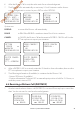
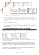
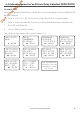
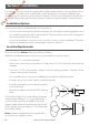
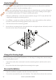
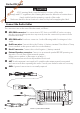
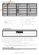
Table Of Contents
- Section 1 - General Information
- Section 2 - The Radio Menu (MENU)
- Section 3 - Radio Setup Menu (RADIO SETUP)
- Section 4 - DSC Setup Menu (DSC SETUP)
- 4-1 DSC Setup - Menu Options
- 4-2 Enter or View Your USER MMSI (USER MMSI)
- 4-3 Maintain Your Groups (GROUP SETUP)
- 4-4 Response to Individual Calls (INDIV REPLY)
- 4-5 ATIS MMSI & ATIS Functionality
- 4-6 DSC functionality options (DSC FUNC)
- 4-7 Response Type to LL Polling Calls (LL REPLY)
- 4-8 Automatic Channel switching (AUTO SWITCH)
- 4-9 DSC Test Reply (TEST REPLY)
- 4-10 Set the inactivity timer (TIMEOUT)
- 4-1 DSC Setup - Menu Options
- Section 5 - Sending and Receiving DSC Calls
- 5-1 What is DSC?
- 5-2 Sending DSC calls
- 5-2-1 Make a Routine Call (INDIVIDUAL)
- 5-2-2 Retrying a Routine Call
- 5-2-3 Acknowledgement of an Individual Incoming Call (INDIV)
- 5-2-4 Recall the Most Recent Incoming Call (LAST CALL)
- 5-2-5 Call a Group (GROUP)
- 5-2-6 Call All Ships (ALL SHIPS)
- 5-2-7 Call using the Call Log (CALL LOG)
- 5-2-8 Call using the Distress Log (DISTR LOG)
- 5-2-9 Call using the Sent Call Log (SENT CALL)
- 5-2-10 Request the LL Position of a Buddy (LL REQUEST)
- 5-2-11 Make a DSC test call (DSC TEST)
- 5-3 Receiving DSC Calls
- 5-2 Sending DSC calls
- 5-1 What is DSC?
- Section 6 - Distress Calls
- Section 7 - Installation
- Appendix A - Technical Specifications
- Appendix B - Troubleshooting
- Appendix C - US & ROW VHF Marine Channel Charts
- Appendix D - EU VHF Marine Channel Charts
- Appendix E - MMSI, FCC and License Information

Lowrance | Link-5 VHF User Guide 49
Set Up the Radio
The user MMSI is a unique nine digit number, similar to a personal telephone number. It is
used on marine transceivers that are capable of using DSC (Digital Select Calling).
If you don’t have a user MMSI contact the appropriate authorities in your country. If you’re
unsure who to contact, consult your Lowrance dealer.
• A Group MMSI begins with 0 followed by 8 numeric digits (0xxxxxxxx)
• A Coast Station MMSI begins with 00 followed by 7 numeric digits. You just need to add
the 7 digits and the radio will add the beginning 00 for you
Enter Your User MMSI
See section 4-2 Enter Your USER MMSI (USER MMSI).
CAUTION
You can’t make any DSC transmissions until you’ve obtained a user MMSI and entered it
into your radio.
Wiring for GPS/COM connector
Pin Wire Function Notes
1 Red
No connection (Not used)
2 Orange OUT (+) ( To )
3 White Program/clone
(Not used)
4 Green IN (-) (From )
5 Yellow IN (+) (From )
6 Black OUT (-) (Ground)
7 Blue
No connection (Not used)
8 Grey
No connection (Not used)
8 Grey
2 Orange
4 Green
1 Bare wire
6 Black
5 Yellow
3 White
7 Blue
Draft - Final approval