
User's Manual
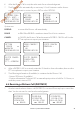
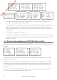
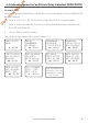
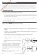
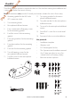
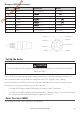
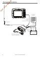
Table Of Contents
- Section 1 - General Information
- Section 2 - The Radio Menu (MENU)
- Section 3 - Radio Setup Menu (RADIO SETUP)
- Section 4 - DSC Setup Menu (DSC SETUP)
- 4-1 DSC Setup - Menu Options
- 4-2 Enter or View Your USER MMSI (USER MMSI)
- 4-3 Maintain Your Groups (GROUP SETUP)
- 4-4 Response to Individual Calls (INDIV REPLY)
- 4-5 ATIS MMSI & ATIS Functionality
- 4-6 DSC functionality options (DSC FUNC)
- 4-7 Response Type to LL Polling Calls (LL REPLY)
- 4-8 Automatic Channel switching (AUTO SWITCH)
- 4-9 DSC Test Reply (TEST REPLY)
- 4-10 Set the inactivity timer (TIMEOUT)
- 4-1 DSC Setup - Menu Options
- Section 5 - Sending and Receiving DSC Calls
- 5-1 What is DSC?
- 5-2 Sending DSC calls
- 5-2-1 Make a Routine Call (INDIVIDUAL)
- 5-2-2 Retrying a Routine Call
- 5-2-3 Acknowledgement of an Individual Incoming Call (INDIV)
- 5-2-4 Recall the Most Recent Incoming Call (LAST CALL)
- 5-2-5 Call a Group (GROUP)
- 5-2-6 Call All Ships (ALL SHIPS)
- 5-2-7 Call using the Call Log (CALL LOG)
- 5-2-8 Call using the Distress Log (DISTR LOG)
- 5-2-9 Call using the Sent Call Log (SENT CALL)
- 5-2-10 Request the LL Position of a Buddy (LL REQUEST)
- 5-2-11 Make a DSC test call (DSC TEST)
- 5-3 Receiving DSC Calls
- 5-2 Sending DSC calls
- 5-1 What is DSC?
- Section 6 - Distress Calls
- Section 7 - Installation
- Appendix A - Technical Specifications
- Appendix B - Troubleshooting
- Appendix C - US & ROW VHF Marine Channel Charts
- Appendix D - EU VHF Marine Channel Charts
- Appendix E - MMSI, FCC and License Information

Lowrance | Link-5 VHF User Guide 45
1. Mounting gimbal for the VHF radio
2. GPS connection cable
3. Two mounting knobs
4. Microphone bulkhead mount
5. Four countersunk self-tapping screws
for the mounting gimbal
6. Four flat screws for the mounting
gimbal
7. Four spring washers for the mounting
gimbal
8. Four plain washers for the mounting
gimbal
9. Four nuts for the mounting gimbal
10. Two self-tapping screws for the
microphone bulkhead mount
11. Two flat screws for the microphone
bulkhead mount
12. Two spring washers for the micro-
phone bulkhead mount
13. Two plain washers for the microphone
bulkhead mount
14. Two nuts for the microphone bulkhead
mount
15. Four M5x32 screws for recessed instal-
lation
16. Four nuts for the recessed installation
Not pictured:
• Installation template
• Warranty card
• DSC Warning label sticker
• This Operation and Installation manual
• One 7 Amp spare fuse in case of ac-
cidental reverse of battery polarity
• Base unit and microphone
Checklist
The following items should be supplied in the box. Check before starting the installation and
contact your dealer if an item is missing.
Note: An antenna is not provided. Consult your Lowrance dealer for advice if necessary.
1
3
2
15
5
6
7
8
9
10
11
12
13
14
4
16
Draft - Final approval