
User's Manual
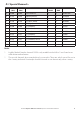
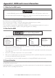
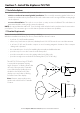
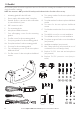
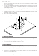
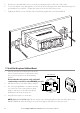
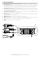
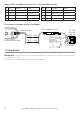
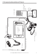
Table Of Contents
- Section 1 - General Information
- Section 2 - The Radio Menu (MENU)
- 2-1 The Radio Menu Options (MENU)
- 2-2 Show Weather, SNR or Happy Fish on Handset (INFO DATA)
- 2-3 Maintain Your Buddy List (BUDDY LIST)
- 2-4 Local or Distance Sensitivity (LOCAL/DIST)
- 2-5 Backlighting (BACKLIGHT) and Contrast (CONTRAST)
- 2-6 GPS Data and Time (GPS/DATA)
- 2-7 GPS Simulator (GPS SIM)
- 2-8 Reset to Factory Defaults (RESET)
- 2-9 Subscribe or Un-Subscribe the 705 handset (HS SETTING)
- Section 3 - Radio Setup Menu (RADIO SETUP)
- 3-1 The Radio Setup Menu Options (RADIO SETUP)
- 3-2 Select the Channel Bank (UIC) (US only)
- 3-3 Change Channel Names (CH NAME)
- 3-4 Ring and Beep Volume (RING VOLUME and KEY BEEP)
- 3-5 Internal Speaker Connections (INT SPEAKER)
- 3-6 Set the Priority Channel (WATCH MODE)
- 3-7 Weather Alert (WX ALERT) (US only)
- 3-8 NMEA or NAVBUS protocol (COM PORT) (721 / 725 only)
- 3-9 Barometric Displays (BARO SENSOR)
- 3-10 Temperature Display (TEMPERATURE)
- 3-11 HAPPY FISH Alarm ON or OFF
- Section 4 - DSC SETUP Menu
- 4-1 What is DSC?
- 4-2 DSC SETUP Menu Options
- 4-3 Check Your User MMSI (USER MMSI)
- 4-4 Maintain Your Groups (GROUP SETUP)
- 4-5 Response to Individual Calls (INDIV REPLY) (US only)
- 4-6 ATIS MMSI & ATIS Functionality (EU only)
- 4-7 DSC Functionality (DSC FUNC)
- 4-8 Response Type to LL Polling Calls (LL REPLY)
- 4-9 Mute the Notification Ringtone
- Section 5 - Send and Receive DSC Calls
- 5-1 The DSC CALL Menu Options
- 5-2 Call an Individual (INDIVIDUAL)
- 5-3 Call the Most Recent Caller (LAST CALL)
- 5-4 Call a Group (GROUP)
- 5-5 Call All Ships (ALL SHIPS)
- 5-6 Call using the Call Log (CALL LOG)
- 5-7 Call using the Distress Log (DIST LOG)
- 5-8 Request the LL Position of a Buddy (LL REQUEST)
- 5-9 Track Your Buddy (TRACK BUDDY)
- 5-10 Receive an All Ships Call (RCV: ALL SHIP)
- 5-11 Receive an Individual Call (RCV: INDIV)
- 5-12 Receive a Group Call (RCV: GROUP)
- 5-13 Receive a Geographic Call (RCV: GEOGRAPH)
- 5-14 Receive a Polled Position Call (RCV:POSITION)
- Section 6 - Distress Calls
- Appendix A - Technical Specifications
- Appendix B - Troubleshooting
- Appendix C - VHF Marine Channel Charts
- Appendix D - EU Inland Waterway Channels
- Appendix E - MMSI and License Information
- Section 7 - Install the Explorer 721/725

62 Northstar Explorer VHF Series: 721/725 Operation and Installation Manual Northstar Explorer VHF Series: 721/725 Operation and Installation Manual
7-9 Set Up the Radio
IMPORTANT: You can’t make any DSC transmissions until you’ve obtained a user MMSI and entered it into
your Explorer 721/725 .
See Appendix E for Obtaining and Entering MMSI information.
Black
Power/data cable
Orange Blue
Blue Grey
Pin Wire Function Notes
1 Red No connection (Not used)
2 Orange NMEA OUT (+) (To GPS)
3 White Program/clone (Not used)
4 Green NMEA IN (-) (From GPS)
Pin Wire Function Notes
5 Yellow NMEA IN (+) (From GPS)
6 Black NMEA OUT (-) (Ground)
7 Blue NAVBUS (+)
8 Grey NAVBUS (-)
Connecting to a Northstar display using NavBus:
GPS and COM connector
721 / 725
Base unit
Northstar GPS product
Wiring for GPS and COM connector (See 7-8, 1. GPS and COM connector)