
User's Manual
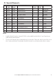
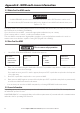
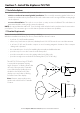
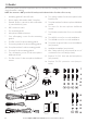
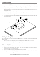
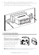
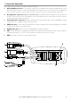
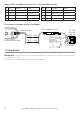
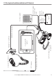
Table Of Contents
- Section 1 - General Information
- Section 2 - The Radio Menu (MENU)
- 2-1 The Radio Menu Options (MENU)
- 2-2 Show Weather, SNR or Happy Fish on Handset (INFO DATA)
- 2-3 Maintain Your Buddy List (BUDDY LIST)
- 2-4 Local or Distance Sensitivity (LOCAL/DIST)
- 2-5 Backlighting (BACKLIGHT) and Contrast (CONTRAST)
- 2-6 GPS Data and Time (GPS/DATA)
- 2-7 GPS Simulator (GPS SIM)
- 2-8 Reset to Factory Defaults (RESET)
- 2-9 Subscribe or Un-Subscribe the 705 handset (HS SETTING)
- Section 3 - Radio Setup Menu (RADIO SETUP)
- 3-1 The Radio Setup Menu Options (RADIO SETUP)
- 3-2 Select the Channel Bank (UIC) (US only)
- 3-3 Change Channel Names (CH NAME)
- 3-4 Ring and Beep Volume (RING VOLUME and KEY BEEP)
- 3-5 Internal Speaker Connections (INT SPEAKER)
- 3-6 Set the Priority Channel (WATCH MODE)
- 3-7 Weather Alert (WX ALERT) (US only)
- 3-8 NMEA or NAVBUS protocol (COM PORT) (721 / 725 only)
- 3-9 Barometric Displays (BARO SENSOR)
- 3-10 Temperature Display (TEMPERATURE)
- 3-11 HAPPY FISH Alarm ON or OFF
- Section 4 - DSC SETUP Menu
- 4-1 What is DSC?
- 4-2 DSC SETUP Menu Options
- 4-3 Check Your User MMSI (USER MMSI)
- 4-4 Maintain Your Groups (GROUP SETUP)
- 4-5 Response to Individual Calls (INDIV REPLY) (US only)
- 4-6 ATIS MMSI & ATIS Functionality (EU only)
- 4-7 DSC Functionality (DSC FUNC)
- 4-8 Response Type to LL Polling Calls (LL REPLY)
- 4-9 Mute the Notification Ringtone
- Section 5 - Send and Receive DSC Calls
- 5-1 The DSC CALL Menu Options
- 5-2 Call an Individual (INDIVIDUAL)
- 5-3 Call the Most Recent Caller (LAST CALL)
- 5-4 Call a Group (GROUP)
- 5-5 Call All Ships (ALL SHIPS)
- 5-6 Call using the Call Log (CALL LOG)
- 5-7 Call using the Distress Log (DIST LOG)
- 5-8 Request the LL Position of a Buddy (LL REQUEST)
- 5-9 Track Your Buddy (TRACK BUDDY)
- 5-10 Receive an All Ships Call (RCV: ALL SHIP)
- 5-11 Receive an Individual Call (RCV: INDIV)
- 5-12 Receive a Group Call (RCV: GROUP)
- 5-13 Receive a Geographic Call (RCV: GEOGRAPH)
- 5-14 Receive a Polled Position Call (RCV:POSITION)
- Section 6 - Distress Calls
- Appendix A - Technical Specifications
- Appendix B - Troubleshooting
- Appendix C - VHF Marine Channel Charts
- Appendix D - EU Inland Waterway Channels
- Appendix E - MMSI and License Information
- Section 7 - Install the Explorer 721/725

61Northstar Explorer VHF Series: 721/725 Operation and Installation Manual
7-8 Connect the Radio Cables
The connectors are on the rear of the base unit, as follows:
1. GPS and COM connector. For connection to GPS device via NMEA. Also includes NavBus wiring for Track
Buddy and other features. See the following table for wiring and color codes. (If you’re not using this, be
sure to put the protective cap securely over the connector to protect it from moisture and dust.)
2. Docking Cable connector (Explorer 721US/EU only) for optional Handset. Plug the docking cable jack
into the connector. (If you’re not using this, be sure to put the protective cap securely over the connector
to protect it from moisture and dust.)
3. External Speaker connector. Plug the external speaker cable jack into the connector BEFORE powering
ontheradio.Usea4Ohm4Wattexternalspeaker.
4. RED Power wire. Connect this to the POSITIVE (+) battery terminal. Check that a 10 Amp fuse is installed
on this power cable close to the battery.
5. BLACK Power wire. Connect this to the NEGATIVE (-) battery terminal.
6. ANT. A radio antenna is not supplied. A suitable radio antenna must be mounted and connected before
operating the Explorer 721/725 radio. Consult your dealer for advice if necessary.
7. GND. A ground connection is not usually required..
1
2
3
4
5
6
7