
User's Manual
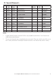
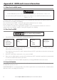
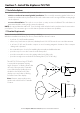
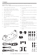
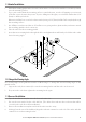
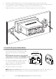
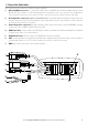
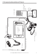
Table Of Contents
- Section 1 - General Information
- Section 2 - The Radio Menu (MENU)
- 2-1 The Radio Menu Options (MENU)
- 2-2 Show Weather, SNR or Happy Fish on Handset (INFO DATA)
- 2-3 Maintain Your Buddy List (BUDDY LIST)
- 2-4 Local or Distance Sensitivity (LOCAL/DIST)
- 2-5 Backlighting (BACKLIGHT) and Contrast (CONTRAST)
- 2-6 GPS Data and Time (GPS/DATA)
- 2-7 GPS Simulator (GPS SIM)
- 2-8 Reset to Factory Defaults (RESET)
- 2-9 Subscribe or Un-Subscribe the 705 handset (HS SETTING)
- Section 3 - Radio Setup Menu (RADIO SETUP)
- 3-1 The Radio Setup Menu Options (RADIO SETUP)
- 3-2 Select the Channel Bank (UIC) (US only)
- 3-3 Change Channel Names (CH NAME)
- 3-4 Ring and Beep Volume (RING VOLUME and KEY BEEP)
- 3-5 Internal Speaker Connections (INT SPEAKER)
- 3-6 Set the Priority Channel (WATCH MODE)
- 3-7 Weather Alert (WX ALERT) (US only)
- 3-8 NMEA or NAVBUS protocol (COM PORT) (721 / 725 only)
- 3-9 Barometric Displays (BARO SENSOR)
- 3-10 Temperature Display (TEMPERATURE)
- 3-11 HAPPY FISH Alarm ON or OFF
- Section 4 - DSC SETUP Menu
- 4-1 What is DSC?
- 4-2 DSC SETUP Menu Options
- 4-3 Check Your User MMSI (USER MMSI)
- 4-4 Maintain Your Groups (GROUP SETUP)
- 4-5 Response to Individual Calls (INDIV REPLY) (US only)
- 4-6 ATIS MMSI & ATIS Functionality (EU only)
- 4-7 DSC Functionality (DSC FUNC)
- 4-8 Response Type to LL Polling Calls (LL REPLY)
- 4-9 Mute the Notification Ringtone
- Section 5 - Send and Receive DSC Calls
- 5-1 The DSC CALL Menu Options
- 5-2 Call an Individual (INDIVIDUAL)
- 5-3 Call the Most Recent Caller (LAST CALL)
- 5-4 Call a Group (GROUP)
- 5-5 Call All Ships (ALL SHIPS)
- 5-6 Call using the Call Log (CALL LOG)
- 5-7 Call using the Distress Log (DIST LOG)
- 5-8 Request the LL Position of a Buddy (LL REQUEST)
- 5-9 Track Your Buddy (TRACK BUDDY)
- 5-10 Receive an All Ships Call (RCV: ALL SHIP)
- 5-11 Receive an Individual Call (RCV: INDIV)
- 5-12 Receive a Group Call (RCV: GROUP)
- 5-13 Receive a Geographic Call (RCV: GEOGRAPH)
- 5-14 Receive a Polled Position Call (RCV:POSITION)
- Section 6 - Distress Calls
- Appendix A - Technical Specifications
- Appendix B - Troubleshooting
- Appendix C - VHF Marine Channel Charts
- Appendix D - EU Inland Waterway Channels
- Appendix E - MMSI and License Information
- Section 7 - Install the Explorer 721/725

60 Northstar Explorer VHF Series: 721/725 Operation and Installation Manual Northstar Explorer VHF Series: 721/725 Operation and Installation Manual
5. Use the two short M5x10 screws to screw the mounting brackets to the sides of the radio.
6. Screw each M5x32 screw through the screw hole in the mounting bracket, then attach the stopper. If
your bulkhead exceeds 0.51” (13mm), the stopper can be discarded if necessary.
7. Tighten the M5x32 screws until the radio is held firmly against the rear of the bulkhead.
7-7 Install the Microphone Bulkhead Mount
1. Hold the microphone bulkhead mount at the
chosen location and use a soft pencil to mark
the screw hole positions on the mounting
surface.
Ensure that the microphone curly cable will
comfortably reach this location BEFORE you drill.
2. Drill the two pilot screw holes where marked.
3. Use a short length Philips screwdriver and the
set of two flat screws, spring washers, plain
washers, and nuts to secure the microphone
bulkhead mount at the location
site.
4. Hangthemicrophoneonitsmount.
NOTE: (Explorer 721US/EU only) This mic clip has a special magnet glued in the rear of the clip to sense
ON/OFF HOOK. All other mic hangers do not have magnets and therefore cannot be used.
MM
MM
MM