
User's Manual
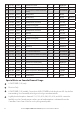
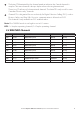
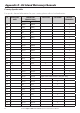
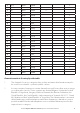
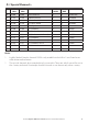
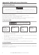
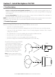
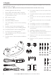
Table Of Contents
- Section 1 - General Information
- Section 2 - The Radio Menu (MENU)
- 2-1 The Radio Menu Options (MENU)
- 2-2 Show Weather, SNR or Happy Fish on Handset (INFO DATA)
- 2-3 Maintain Your Buddy List (BUDDY LIST)
- 2-4 Local or Distance Sensitivity (LOCAL/DIST)
- 2-5 Backlighting (BACKLIGHT) and Contrast (CONTRAST)
- 2-6 GPS Data and Time (GPS/DATA)
- 2-7 GPS Simulator (GPS SIM)
- 2-8 Reset to Factory Defaults (RESET)
- 2-9 Subscribe or Un-Subscribe the 705 handset (HS SETTING)
- Section 3 - Radio Setup Menu (RADIO SETUP)
- 3-1 The Radio Setup Menu Options (RADIO SETUP)
- 3-2 Select the Channel Bank (UIC) (US only)
- 3-3 Change Channel Names (CH NAME)
- 3-4 Ring and Beep Volume (RING VOLUME and KEY BEEP)
- 3-5 Internal Speaker Connections (INT SPEAKER)
- 3-6 Set the Priority Channel (WATCH MODE)
- 3-7 Weather Alert (WX ALERT) (US only)
- 3-8 NMEA or NAVBUS protocol (COM PORT) (721 / 725 only)
- 3-9 Barometric Displays (BARO SENSOR)
- 3-10 Temperature Display (TEMPERATURE)
- 3-11 HAPPY FISH Alarm ON or OFF
- Section 4 - DSC SETUP Menu
- 4-1 What is DSC?
- 4-2 DSC SETUP Menu Options
- 4-3 Check Your User MMSI (USER MMSI)
- 4-4 Maintain Your Groups (GROUP SETUP)
- 4-5 Response to Individual Calls (INDIV REPLY) (US only)
- 4-6 ATIS MMSI & ATIS Functionality (EU only)
- 4-7 DSC Functionality (DSC FUNC)
- 4-8 Response Type to LL Polling Calls (LL REPLY)
- 4-9 Mute the Notification Ringtone
- Section 5 - Send and Receive DSC Calls
- 5-1 The DSC CALL Menu Options
- 5-2 Call an Individual (INDIVIDUAL)
- 5-3 Call the Most Recent Caller (LAST CALL)
- 5-4 Call a Group (GROUP)
- 5-5 Call All Ships (ALL SHIPS)
- 5-6 Call using the Call Log (CALL LOG)
- 5-7 Call using the Distress Log (DIST LOG)
- 5-8 Request the LL Position of a Buddy (LL REQUEST)
- 5-9 Track Your Buddy (TRACK BUDDY)
- 5-10 Receive an All Ships Call (RCV: ALL SHIP)
- 5-11 Receive an Individual Call (RCV: INDIV)
- 5-12 Receive a Group Call (RCV: GROUP)
- 5-13 Receive a Geographic Call (RCV: GEOGRAPH)
- 5-14 Receive a Polled Position Call (RCV:POSITION)
- Section 6 - Distress Calls
- Appendix A - Technical Specifications
- Appendix B - Troubleshooting
- Appendix C - VHF Marine Channel Charts
- Appendix D - EU Inland Waterway Channels
- Appendix E - MMSI and License Information
- Section 7 - Install the Explorer 721/725

58 Northstar Explorer VHF Series: 721/725 Operation and Installation Manual Northstar Explorer VHF Series: 721/725 Operation and Installation Manual
7-3 Checklist
The following items should be supplied in the box. Check before starting the installation and contact your
dealer if an item is missing.
NOTE: An antenna is NOT provided. Consult your Northstar dealer for advice if necessary.
1
3
4
2
6
5
7
8
9
10
11
12
13
14
15
16
17
18 & 19
1. Mounting gimbal for the VHF radio
2. Power supply cable with in built 7 Amp fuse
3. External speaker connection cable with white
(+) wire and black (-) wire
4. GPSconnectioncable
5. Two mounting knobs
6. Microphone bulkhead mount
7. Four self-tapping screws for the mounting
gimbal
8. Four flat screws for the mounting gimbal
9. Four spring washers for the mounting gimbal
10. Four plain washers for the mounting gimbal
11. Four nuts for the mounting gimbal
12. Two self-tapping screws for the microphone
bulkhead mount
13. Two flat screws for the microphone bulkhead
mount
14. Twospringwashersforthemicrophonebulk-
head mount
15. Two plain washers for the microphone bulkhead
mount
16. Two nuts for the microphone bulkhead
mount
17. Two flush-mount brackets for recessed installa-
tion
18. Two M5x32 screws for recessed installation
19. Two M5x10 screws for recessed installation
20. Two plastic stoppers for the recessed installation
(not pictured)
21. Installation template (not pictured)
22. One 7 Amp spare fuse (not pictured) in case of
accidental reverse of battery polarity
23. Explorer 721/725 base unit and microphone
(not pictured)
24. Explorer 721/725 protective cover (not pic-
tured)