
User's Manual
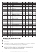
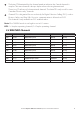
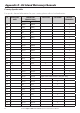
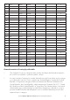
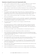
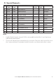
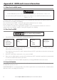
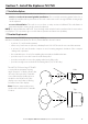
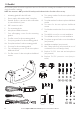
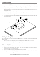
Table Of Contents
- Section 1 - General Information
- Section 2 - The Radio Menu (MENU)
- 2-1 The Radio Menu Options (MENU)
- 2-2 Show Weather, SNR or Happy Fish on Handset (INFO DATA)
- 2-3 Maintain Your Buddy List (BUDDY LIST)
- 2-4 Local or Distance Sensitivity (LOCAL/DIST)
- 2-5 Backlighting (BACKLIGHT) and Contrast (CONTRAST)
- 2-6 GPS Data and Time (GPS/DATA)
- 2-7 GPS Simulator (GPS SIM)
- 2-8 Reset to Factory Defaults (RESET)
- 2-9 Subscribe or Un-Subscribe the 705 handset (HS SETTING)
- Section 3 - Radio Setup Menu (RADIO SETUP)
- 3-1 The Radio Setup Menu Options (RADIO SETUP)
- 3-2 Select the Channel Bank (UIC) (US only)
- 3-3 Change Channel Names (CH NAME)
- 3-4 Ring and Beep Volume (RING VOLUME and KEY BEEP)
- 3-5 Internal Speaker Connections (INT SPEAKER)
- 3-6 Set the Priority Channel (WATCH MODE)
- 3-7 Weather Alert (WX ALERT) (US only)
- 3-8 NMEA or NAVBUS protocol (COM PORT) (721 / 725 only)
- 3-9 Barometric Displays (BARO SENSOR)
- 3-10 Temperature Display (TEMPERATURE)
- 3-11 HAPPY FISH Alarm ON or OFF
- Section 4 - DSC SETUP Menu
- 4-1 What is DSC?
- 4-2 DSC SETUP Menu Options
- 4-3 Check Your User MMSI (USER MMSI)
- 4-4 Maintain Your Groups (GROUP SETUP)
- 4-5 Response to Individual Calls (INDIV REPLY) (US only)
- 4-6 ATIS MMSI & ATIS Functionality (EU only)
- 4-7 DSC Functionality (DSC FUNC)
- 4-8 Response Type to LL Polling Calls (LL REPLY)
- 4-9 Mute the Notification Ringtone
- Section 5 - Send and Receive DSC Calls
- 5-1 The DSC CALL Menu Options
- 5-2 Call an Individual (INDIVIDUAL)
- 5-3 Call the Most Recent Caller (LAST CALL)
- 5-4 Call a Group (GROUP)
- 5-5 Call All Ships (ALL SHIPS)
- 5-6 Call using the Call Log (CALL LOG)
- 5-7 Call using the Distress Log (DIST LOG)
- 5-8 Request the LL Position of a Buddy (LL REQUEST)
- 5-9 Track Your Buddy (TRACK BUDDY)
- 5-10 Receive an All Ships Call (RCV: ALL SHIP)
- 5-11 Receive an Individual Call (RCV: INDIV)
- 5-12 Receive a Group Call (RCV: GROUP)
- 5-13 Receive a Geographic Call (RCV: GEOGRAPH)
- 5-14 Receive a Polled Position Call (RCV:POSITION)
- Section 6 - Distress Calls
- Appendix A - Technical Specifications
- Appendix B - Troubleshooting
- Appendix C - VHF Marine Channel Charts
- Appendix D - EU Inland Waterway Channels
- Appendix E - MMSI and License Information
- Section 7 - Install the Explorer 721/725

57Northstar Explorer VHF Series: 721/725 Operation and Installation Manual
Section 7 - Install the Explorer 721/725
7-1 Installation Options
There are two ways to install the radio. You can choose:
• a deck or overhead mounted gimbal installation. The reversible mounting gimbal is fixed to a
suitable site and the radio is placed into it. The radio can be removed for storage and the viewing angle
can be adjusted.
• a recessed installation. The radio is recessed into a cavity cut into a bulkhead. The radio fixture is
permanent and the viewing angle cannot be adjusted.
NOTE: An optional handset with a 9.8` (3 m) docking cable included can be purchased and connected to
your Explorer 721 base unit to give second station operation and intercom capability.
7-2 Location Requirements
Please check these BEFORE doing any cutting or drilling.
Whichever installation method you choose, ensure that the chosen location:
• isatleast3'(1m)fromtheantenna
• allowseasyconnectionto(atleast)a10Ampfused13.6VDCelectricalsourceandtheantenna
• isatleast1.5'(45cms)fromthecompasstoavoidcreatingmagneticdeviation of the compass
during radio operation
• hasasuitablespaceclosebyforinstallingthemicrophonebulkheadmount
• provideseasyaccesstothecontrolsonthefrontpanel
• providesreasonableaccesstothewiringatthebackoftheradio
• providesenoughroomtoxtheDSCwarninglabel(721/725USonly).
The VHF721/725 has a large FSTN LCD
screen with an optimum viewing
angle of approx. +/-20 deg. Ensure the
chosen location provides a suitable
view of the display. Ideally, the user
should be directly in front of the
display or no more than +/-20 deg
from the front of the display.
Note: If unsure, temporarily power
up the radio and check for a suitable
location.
20˚
20˚
20˚
20˚
Side
Top