
User's Manual


12 |
About your AIS class B transceiver | NAIS-400 Instruction Manual
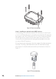
Fixing screws
Four fixing screws are provided with the product for mounting of
the AIS transceiver. Please refer to the Installation procedures, chap-
ter 3 for details of how to mount the AIS transceiver.
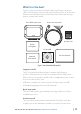
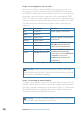
AIS transceiver unit
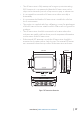
Figure 2 shows an overview of the AIS transceiver unit.
The AIS transceiver has a number of indicators which provide in-
formation to the user about the status of the AIS transceiver. Please
refer to Indicator functions, chapter 5 for more details.
The AIS transceiver has an internal GPS antenna. You should ensure
that the transceiver is mounted where it has a clear view of the sky,
or you can alternatively connect an external GPS antenna, which is
available from your dealer as an accessory.
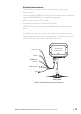
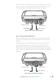
Power, data and USB cable
The power and data cable connects to the AIS transceiver and en-
ables connection to power, NMEA0183, external silent mode switch
and USB.
Warning: Do not attempt to adjust or remove the fixings
next to each of the four mounting holes. These fixings form part
of the sealing of the AIS transceiver and any modification could
affect the product’s performance and will invalidate the prod-
uct’s warranty.
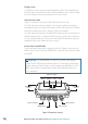
Green Amber Red Blue
Power and data
GPS antenna
NMEA 2000 VHF antenna
Indicator lights
Mounting
holes
Mounting
holes
Figure 2 AIS transceiver overview