in ar y Installation Manual Navico Broadband Radar BR-24 Pr el im English Preliminary www.lowrance.com www.northstarnav.com. www.simrad-yachting.
in ar y im el Pr Navico Radar Broadband Installation manual English, Doc.no.
1 Preface FCC Statement Note: This equipment has been tested and complies with the limits for a Class B digital device, pursuant to Part 15 of the FCC Rules. These limits are designed to provide reasonable protection against harmful interference in a normal installation. This equipment generates, uses and can radiate radio frequency energy and, if not installed and used in accordance with the instructions, may cause harmful interference to radio communications.
Disclaimer As Navico is continuously improving this product, we retain the right to make changes to the product at any time which may not be reflected in this version of the manual. Please contact your nearest distributor if you require any further assistance. It is the owner’s sole responsibility to install and use the instrument and transducers in a manner that will not cause accidents, personal injury or property damage. The user of this product is solely responsible for observing safe boating practices.
Contents 1 Preface ........................................................................................................ 1 FCC Statement ............................................................................................. 1 Industry Canada ........................................................................................... 1 CE Compliance ............................................................................................. 1 Disclaimer .............................................
Drawings ................................................................................................... 23 Radar interface box..................................................................................... 23 Scanner dimensions .................................................................................... 24 7 Specifications ............................................................................................ 25 8 Navico Broadband radar part numbers ................................
2 Introduction to the Navico Broadband radar system What is Broadband radar? The Navico Broad band radar uses FMCW (Frequency Modulated Continuous Wave) radar technology What is FMCW? FMCW radar is different: in ar y The current normal leisure radar generates microwave pulses with a thermionic device called a magnetron. This ancient technology sends out bursts of high power microwave energy periodically, and the radar detector listens to the echoes coming back from each pulse.
The difference in the currently transmitted and currently received frequencies, coupled with the known rate of frequency increase, allows a time of flight to be calculated, from which distance is calculated Benefits of FMCW radar Safer • low energy emissions, similar to a cell phone • more flexibility in placement on boat • can run in anchorages and marinas Short range performance • Conventional radars can not see anything closer than 30 meters • FMCW can see within a few meters of the boat • See th
Radar system overview The Navico Broadband radar is a state of the art navigation aid providing outstanding radar performance with out the limitations of conventional pulse radars such as dangerous high power microwaves, Standby warm up time, high power consumption and large open arrays which is what would be required to obtain the same image quality at shorter ranges . The Navico Broadband radar as an effective range from 1/16 to 24 nm. and has an operating power consumption of 17 W.
3 Install the radar Installation includes: • mechanical mounting • electrical wiring • configuring the display or network system to work with the radar • adjusting the radar for proper performance Don't take any shortcuts, and follow these instructions carefully! This section explains how to: • choose the correct location for the scanner install the scanner on a power boat or a yacht • choose the correct location for the radar processor • install the radar processor Check the parts in ar y •
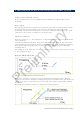
Choose the scanner location The radar's ability to detect targets depends greatly on the position of its scanner. The ideal location for the scanner is high above the vessel's keel line where there are no obstacles. A higher installation position increases the radar ranging distance, but it also increases the minimum range around the vessel where targets cannot be detected.
Mounting the scanner • Use the supplied mounting template and tape it securely to the chosen location site. • Before drilling, check that: - you have oriented the mounting template correctly so that the front of the scanner unit will face the front of the vessel - the location site is not more than 15 mm (0.6") thick. If the location site is thicker use longer bolts Note: The bolts supplied are M8 x 30 mm x 4.
Mounting the radar interface box Install the radar interface box in a dry location away from spray, rain, drips and condensation. • The radar processor must be located where it can be easily connected to the ship's ground, the scanner interconnection cable, a power source and the display or display network. • Allow enough room for cables to form a drip loop. • Preferably mount the radar interface box on a vertical surface with cables exiting downwards.
4 Wiring the radar system Connect interconection cable to the scanner The scanner interconnection cable connects the scanner to the RI-10 or RI-11 interface box (or Lowrance HDS U.S only). The cable connects to the scanner using a 14 pin connector. Insert cable connector on to the male 14 pin plug on the scanner. take care to align the connector correctly to avoid bending the pins.
screw the lock nut on to the gland housing Key in ar y • Description Lock nut B Gland washer C Screws x 4 M3x12mm phillips pan head D Cable gland housing E Power wires (see "Connect power" page 14) F Radar data connector RJ45 el im A Radar interface box SR000041-G AA010204 (Serial) AA010189 (Network) Pr G Part Number Wiring the radar system | 13
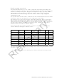
Shortening the cable It is not recommended to shorten the cable but if it is essential use the pin-out below to reterminate the RJ45 connector RJ45 Connector Pin White/Orange 2 Orange 3 White/Green 4 Blue 5 White/Blue Green 7 White/Brown 8 Brown in ar y 6 15 mm Heat shrink (10 mm dia) im RJ45 Connector Colour 1 Connect power Before connecting power to the system: make sure the scanner has been installed and is secured • make sure the scanner cable is connected to the scanner • if
in ar y For systems that do not require a Radar Interface Box, connect power directly to the scanner cable.
Connect the Broadband radar to your display Lowrance HDS (U.S only) Broadband scanner Adapter cable HDS Display ENET Port in ar y 000-0127-56 0.6 m (2 ft) Optional 5 port switch Lowrance broadband in the US market does not require a Radar interface box. the scanner connects directly the display or ethernet switch via the adaptor cable im Lowrance HDS (Non U.
RI-11 NETWORK port Adaptor cable Ethernet cable 000-0127-56 AA000056 8 port Ethernet linker (or cross-over cable) NETWORK port AA010009 (AA010084 in ar y Connects to 8000i system via ethernet. Connect 8000i ethernet cable in between 8 port linker (or crossover cable) and supplied adaptor cable. NX40 and NX 45 M84 and M121 Data cable NX or M series AA010114 3m (9.
SimNet heading sensor in ar y Connecting a heading sensor SimNet to NMEA converter HDS NMEA 2K port FC40 or RC42 Pr el im GB40 SimNet heading sensor RI-10 GB40 Navcomputer FC40 or RC42 SimNet port SimNet port For MARPA functionality on GB40 heading information at 10 Hz needs to be sent to both the RI-11 and the GB40 NavComputer.
SimNet heading sensor FC40 or RC42 in ar y NX 40, NX45 AT40 or AT45 SimNet to NMEA 0183 converter NX 40 or NX45 GPS port For accurate radar chart overlay a heading sensor on the SimNet backbone passes thought the AT40 or AT45 which connects to the GPS port on the NX display 8000i NMEA 0183 el im 12" Display processor, Black box processor, Simrad GB40 not using a SimNet heading sensor Junction Box RI-11 8000i navcomputer COMMS port Utility port Pr NMEA0183 Heading Sensor For MARPA functional
M-84 and M-121 Juncti on box RI-11 Connection kit M-84 or M121 Display COMMS port AA010112 Radar port in ar y NMEA0183 heading sensor Pr el im For accurate radar overlay use an NMEA0183 heading sensor.
5 Configure displays to use radar Setup and configuration of the Broadband radar has been simplified compared to traditional pulse radars. There is no warm up time or burn in required. there is no "main bang" setup. The only adjustment needed is to • Set the scanner height: This is to help the radar calculate for sea clutter • Adjust the heading marker.
• Select Adjust Radar, then select Installation. • The Bearing Alignment button shows the current setting. Select it to change the setting. Use the Up and Down buttons to move the radar image one degree at a time, until the radar overlay is aligned with the chart. • Select OK. • Select Return. Simrad NX40/45 or Northstar M84/M121 radar setup When the radar is enabled, it will turn on, warm up, and enter standby mode.
6 Drawings Pr el im in ar y Radar interface box Drawings | 23
Pr el im in ar y Scanner dimensions Key 24 | Drawings Description A Cable entry area B Cable retention channel C Bolt holes x 4 M8 x 30 mm D Breather
7 Specifications Characteristic Technical Data General Compliance FCC/IC/R&TTE/AUS Type Certification pending FCC ID: RAYBR24 IC ID: 4697A-BR24 Environmental IEC60945 4th edition 2002-2008 Operating Temperature: -25° to +55°C Relative humidity: +35° C, 95% RH Relative wind velocity Power consumption in ar y Waterproof: IPX6 36.0 m/sec (Max:70 Knots) Operating: 17 W (Typ.) @ 13.8 Vdc Standby: 1.6 W (Typ.) @ 13.8 Vdc - only 110 ma DC input (at end of radar cable) 9 V to 31.
8 Navico Broadband radar part numbers Broadband radar scanner part numbers Model Part Number Description Length BR24 AA010186 Broad band radar scanner RI-10 AA010189 Broadband radar SimNet interface box RI-11 AA010204 Broadband radar serial interface box AA010211 Broadband scanner interconnection cable 10 m (33 ft) AA010212 Broadband scanner interconnection cable 20 m (65.6 ft) AA010213 Broadband scanner interconnection cable 30 m (98.
9 Maintenance Clean the radome using soapy water and a soft cloth. avoid using abrasive cleaning products. Do not use solvents such as gasoline, acetone, M.E.K etc.
Navico Broadband Radar BR-24 Installation manual English, Doc.no.