Solar Home and RV Kit 400 Watt And 800 Watt Version Owner’s Manual
Page 2
For safe and optimum performance, the Solar Home and RV Kit must be used properly. Carefully read and follow all instructions and guidelines in this manual and give special attention to the CAUTION and WARNING statements.
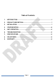
Table of Contents 1. INTRODUCTION ................................................................................................. 5 2. PRODUCT DESCRIPTION ................................................................................. 7 3. INSTALLATION ................................................................................................... 7 4. CONFIGURATION ............................................................................................. 10 5. UNIT OPERATION ............
1. INTRODUCTION Thank you for purchasing the NATURE POWER Solar Home and RV Kit. With our state of the art, easy to use design, this product will offer you reliable service for providing a solar-powered rechargeable power source for your home, cabin, or campsite. With its highly technical design and comprehensive features, the NATURE POWER Solar Home and RV Kit will provide you with a simple yet effective user experience as you learn to generate your own power.
as regular wall AC sockets at home. WARNING: Explosion hazard! DO NOT use the NATURE POWER Solar Home and RV Kit in the vicinity of flammable fumes or gases (such as propane tanks or large engines). AVOID covering the ventilation openings. Always operate unit in an open area. Prolonged contact to high heat or freezing temperatures will decrease the working life of the unit. Unit exposure to these elements may lead to cracking and decreased capacity of the internal battery.
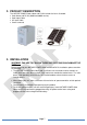
2. PRODUCT DESCRIPTION The NATURE POWER Solar Home and RV Kit includes the items list below. Solar Home and RV Kit (400W and 800W version) Solar Input Cable AC Input Cable Owner‟s manual 3. INSTALLATION WARNING: FAILURE TO FOLLOW THESE INSTRUCTIONS CAN DAMAGE THE UNIT.
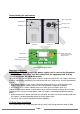
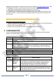
Understanding the unit features Input circuit breaker USB Output AC Input socket AC Outputs Solar Input Port Front view Rear view „Power‟ button „Select‟ button used for feature setting and display function „Status‟ indicator „Solar Charge‟ indicator Control and Display Panel Main Unit Installation IMPORTANT: The AC plug on the power supply cord is used as the disconnect device. The socket-outlet shall be installed near the equipment and shall be easily accessible for rapid disconnect.
(17.5V 8A) that provides an alternative method to charge the internal battery. It is designed to be used with the optional NATURE POWER solar panels (please check our website for solar panel options). If a non-NATURE POWER Solar Home and RV Kit panel is used, be sure the solar panel is designed for a 12V battery system with 8A maximum current, 17.5V rated voltage and open circuit voltage less than 26 VDC. Please refer to the specifications label on the solar panel before connecting.
appropriate crimping tools are required. Please check on website www.andersonpower.com under the Powerpole Connectors section for parts details and the wire crimping methods. PP45 Red Connector Housing & 45 amp Contact (1 pc): P/N 1345 PP45 White Connector Housing & 45 amp Contact (1 pc): P/N 1345G7 The red connector is used to connect to the positive terminal of the Solar Home and RV Kit and the white connector is used to connect to the negative (ground) terminal of the Solar Home and RV kit system.
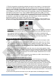
In2 AL1 Backup Priority In2 AL0 Backup Priority with Alarm Disabled Backup Disabled In0 AL1 In0 AL0 Backup & Alarm Disabled Unit will provide output using battery and solar power as higher priority. AC output will only switch to utility mode when battery is low and available. Audio alarm is enabled and will sound when any warning or fault occur. Only use this mode when there is sufficient solar power to power up the load. Same as “Backup Priority” mode but with alarm disabled.
5. UNIT OPERATION WARNING: RISK OF EQUIPMENT DAMAGE Do not plug surge-protected power bars into the unit‟s 120 VAC outlets. The surge protected components on the surge-protected power bar may not like the modified sine wave output generated by the unit. Do not connect an AC power source such as utility power or a generator to the 120 VAC outlets. Do not connect the unit‟s AC power input cord to its 120 VAC outlets.
disconnected unless the AC plug on the unit is removed and the „Power‟ button is held for a second to turn unit off. Using the USB port The USB port on the system provides standard 5V 750mA power to power up USB powered handheld device. AC Load on Solar Home and RV Kit System Although the unit can provide high surge power up to two times the rated output power, some appliances may still trigger the unit‟s protection system.
E02 E03 E04 E05 E06 E07 E08 09 E10 System senses battery voltage is high and has shutdown. System AC output is overloaded or short circuited and has shutdown. System senses high internal temperature and has shutdown System warns battery voltage is low and will shut down shortly System warns AC load connected is close to overload shutdown limit. System warns of high internal temperature and will shut down shortly.
6. TROUBLESHOOTING To trouble shoot the unit, please note the error code displayed on the main unit and review the “Understanding the Error Codes” in section 5.
AC Input Protection (Supplementary Breaker): Transfer Switch Rating: Internal AC Charger Specification: Output Current: Output Voltage (Absorption/Float): Recharge Voltage: Efficiency: Charger type: Solar Charge: Output Current: Output Voltage: Recharge Voltage: Input DC Voltage: Efficiency: Charger Type: Battery Specification: Battery Capacity: Battery Type: Regulatory Approval (ETL certify): 10A 10A 15A 15A 2 ADC 14.8/13.5 VDC 12.6 VDC 80% 3 stages (bulk/absorption/float) 8A maximum 14.8/13.5 VDC 12.
manufacturer will repair the unit or, at its option, replace it, free of charge. If the unit is repaired, new or reconditioned replacement parts may be used, at manufacturer‟s option. A unit may be replaced with a new or reconditioned unit of the same or comparable design. The repaired or replaced unit will then be warranted under these terms for the remainder of the warranty period. The customer is responsible for the shipping charges on all returned items.