Click here to comment on this document via the National Instruments website at http://www.natinst.com/documentation/daq/ VXI-MIO Series User Manual Multifunction I/O Modules for VXIbus August 1996 Edition Part Number 321246A-01 Copyright 1996 National Instruments Corporation. All Rights Reserved.
Internet Support GPIB: gpib.support@natinst.com DAQ: daq.support@natinst.com VXI: vxi.support@natinst.com LabVIEW: lv.support@natinst.com LabWindows: lw.support@natinst.com HiQ: hiq.support@natinst.com Lookout: lookout.support@natinst.com E-mail: info@natinst.com FTP Site: ftp.natinst.com Web Address: http://www.natinst.
Important Information Warranty The VXI-MIO Series boards are warranted against defects in materials and workmanship for a period of one year from the date of shipment, as evidenced by receipts or other documentation. National Instruments will, at its option, repair or replace equipment that proves to be defective during the warranty period. This warranty includes parts and labor.
Table of Contents About This Manual Organization of This Manual ........................................................................................xi Conventions Used in This Manual ................................................................................xii National Instruments Documentation ...........................................................................xiii Related Documentation .................................................................................................
Table of Contents Chapter 3 Hardware Overview Analog Input ................................................................................................................. 3-3 Input Mode ..................................................................................................... 3-3 Input Polarity and Input Range ...................................................................... 3-4 Considerations for Selecting Input Ranges ...................................... 3-6 Dither ...................
Table of Contents Power Connections ........................................................................................................4-23 Timing Connections ......................................................................................................4-23 Programmable Function Input Connections ...................................................4-24 Data Acquisition Timing Connections ...........................................................4-25 SCANCLK Signal .............................
Table of Contents Appendix A Specifications VXI-MIO-64E-1 ........................................................................................................... A-1 VXI-MIO-64XE-10 ...................................................................................................... A-10 Appendix B Optional Cable Connector Descriptions Appendix C Common Questions Appendix D Customer Communication Glossary Index Figures Figure 1-1.
Table of Contents Figure 4-1. I/O Connector Pin Assignment for the VXI-MIO-64E-1 and VXI-MIO-64XE-10 ................................................................................4-2 Figure 4-2. VXI-MIO Series PGIA ............................................................................4-10 Figure 4-3. Summary of Analog Input Connections ..................................................4-13 Figure 4-4. Differential Input Connections for Ground-Referenced Signals .............4-15 Figure 4-5.
Table of Contents Tables Table 2-1. VXI-MIO Series DRAM Configuration .................................................. 2-6 Table 3-1. Table 3-2. Table 3-3. Available Input Configurations for the VXI-MIO Series ....................... 3-3 Actual Range and Measurement Precision .............................................. 3-4 Actual Range and Measurement Precision, VXI-MIO-64XE-10 ........... 3-6 Table 4-1. Table 4-2. VXI-MIO-64E-1 I/O Signal Summary .................................................
About This Manual This manual describes the electrical and mechanical aspects of each module in the VXI-MIO Series product line and contains information concerning their installation, operation, and programming. Unless otherwise noted, text applies to all modules in the VXI-MIO Series. The VXI-MIO Series includes the following modules: • VXI-MIO-64E-1 • VXI-MIO-64XE-10 The VXI-MIO Series modules are high-performance multifunction analog, digital, and timing I/O modules for VXIbus.
About This Manual • Appendix C, Common Questions, contains a list of commonly asked questions and their answers relating to usage and special features of your VXI-MIO Series module. • Appendix D, Customer Communication, contains forms you can use to request help from National Instruments or to comment on our products. • The Glossary contains an alphabetical list and description of terms used in this manual, including acronyms, abbreviations, metric prefixes, mnemonics, and symbols.
About This Manual National Instruments Documentation The VXI-MIO Series User Manual is one piece of the documentation set for your VXI-DAQ system. You could have any of several types of manuals depending on the hardware and software in your system. Use the manuals you have as follows: • Getting Started with SCXI—If you are using SCXI, this is the first manual you should read. It gives an overview of the SCXI system and contains the most commonly needed information for the modules, chassis, and software.
About This Manual Related Documentation The following National Instruments document contains information you may find helpful: • Application Note 025, Field Wiring and Noise Considerations for Analog Signals Customer Communication National Instruments wants to receive your comments on our products and manuals. We are interested in the applications you develop with our products, and we want to help if you have problems with them.
Chapter 1 Introduction This chapter describes the VXI-MIO Series modules, lists what you need to get started, describes the optional software and optional equipment, and explains how to unpack your VXI-MIO Series module. About the VXI-MIO Series Thank you for buying a National Instruments VXI-MIO Series module. The VXI-MIO Series modules are completely VXIplug&playcompatible multifunction analog, digital, and timing I/O modules for VXIbus.
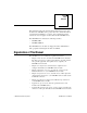
Chapter 1 Introduction What You Need to Get Started To set up and use your VXI-MIO Series module, you will need the following: ❑ One of the following modules: VXI-MIO-64E-1 VXI-MIO-64XE-10 ❑ VXI-MIO Series User Manual ❑ One or more of the following software packages and documentation: ComponentWorks LabVIEW for Windows LabWindows/CVI Measure NI-DAQ for PC Compatibles VirtualBench VXIplug&play instrument driver ❑ Your VXIbus system Software Programming Choices There are several options to choose from w
Chapter 1 Introduction LabVIEW features interactive graphics, a state-of-the-art user interface, and a powerful graphical programming language. The LabVIEW Data Acquisition VI Library, a series of VIs for using LabVIEW with National Instruments DAQ hardware, is included with LabVIEW. The LabVIEW Data Acquisition VI Library is functionally equivalent to the NI-DAQ software. LabWindows/CVI features interactive graphics, a state-of-the-art user interface, and uses the ANSI standard C programming language.
Chapter 1 Introduction DAQ devices because it lets multiple devices operate at their peak performance. NI-DAQ also internally addresses many of the complex issues between the computer and the DAQ hardware such as programming interrupts and DMA controllers. NI-DAQ maintains a consistent software interface between its different versions so that you can change platforms with minimal modifications to your code.
Chapter 1 LabVIEW or LabWindows/CVI Introduction Other Application Development Environments VXIplug&play Instrument Driver NI-DAQ Driver Software VISA VXI-DAQ Hardware Figure 1-1.
Chapter 1 Introduction Custom Cabling Mating connectors and a backshell kit for making custom 96-pin cables for your VXI-MIO Series module are available from National Instruments. If you want to develop your own cable, however, the following guidelines may be useful: • For the analog input signals, shielded twisted-pair wires for each signal yields the best results, assuming that you use differential inputs. Tie the shield for each signal pair to the ground reference at the source.
Chapter Configuration and Installation 2 This chapter explains how to configure and install your VXI-MIO Series module. Module Configuration The VXI-MIO Series modules are software-configurable, except for the VXIbus logical address. You must perform two types of configuration on the VXI-MIO Series modules—bus-related configuration and data acquisition-related configuration.
Chapter 2 Configuration and Installation Your VXI-MIO Series module does not support dynamic configuration of its logical address. Ensure that no other statically configurable VXIbus modules have the same logical address as the VXI-MIO Series module. If they do, change the logical address setting of either the VXI-MIO Series module or the other module so that every module in the system has a different associated logical address.
Chapter 2 Configuration and Installation 4 3 2 5 1 1 6 7 8 9 11 1 2 3 DRAM Product Name Assembly Number 4 5 6 10 P3 Serial Number S1 7 8 9 S2 S3 Logical Address Switch 10 P1 11 P2 Figure 2-1.
Chapter 2 Configuration and Installation 4 3 2 1 1 5 6 7 8 11 1 2 3 DRAM Product Name Assembly Number 4 5 6 P3 S1 S2 10 7 8 9 9 S3 Logical Address Switch (U73) Serial Number 10 P1 11 P2 Figure 2-2. VXI-MIO-64XE-10 Block Diagram Figure 2-3 shows the VXI-MIO-64XE-10 switch settings for logical address 2 and 192.
Chapter 2 Configuration and Installation Logical Address Switch Push up for logic 1 Push down for logic 0 1 2 3 4 5 6 7 8 LSB P1 Connector MSB U73 VXI-MIO-64XE-10 Module a. Switch Set to Logical Address 2 (Default) Logical Address Switch Push up for logic 1 Push down for logic 0 1 2 3 4 5 6 7 8 LSB P1 Connector MSB U73 VXI-MIO-64XE-10 Module b. Switch Set to Logical Address 192 Figure 2-3. VXI-MIO-64XE-10 Logical Address Selection SIMM Size Each VXI-MIO module can accommodate up to two 1.
Chapter 2 Configuration and Installation accessible with the cover on. To access the SIMM sockets, perform the following steps: 1. Remove the four screws on the top, the four screws on the bottom, and the three screws on the right-side cover of the metal enclosure. 2. If the SIMMs are 4 MB x 32 bit or larger, set S3 as shown in Figure 2-4a. 3. For SIMMs smaller than 4 MB x 32 bit, set S3 as shown in Figure 2-4b. SIMM Size (Factory Default) SIMM Size (Factory Default) S3 a.
Chapter 2 Table 2-1.
Chapter 2 Configuration and Installation Load User Configuration Load Factory Configuration S2 S2 Figure 2-5. Load User/Factory Configuration Protect/Change Factory Configuration Use switch S1 to change the factory-default configuration settings by permitting writes to the factory settings section of the EEPROM. This switch serves as a safety measure and should not be needed under normal circumstances.
Chapter 2 Configuration and Installation 2. Remove or open any doors or covers blocking access to the mainframe slots. 3. If you are installing your VXI-DAQ module into a D-size mainframe, first install an appropriate support for C-size modules in D-size mainframes. 4. Insert the VXI-DAQ module in the slot you have selected: a. Align the top and bottom of the module with the card-edge guides inside the mainframe. b.
Chapter 2 Configuration and Installation If you are using LabWindows/CVI, refer to your LabWindows/CVI release notes to install your application software. After you have installed LabWindows/CVI, refer to the NI-DAQ release notes and follow the instructions given there for your operating system and LabWindows/CVI. If you are using ComponentWorks, Measure, or VirtualBench application software, refer to your documentation for installation instructions.
Chapter 3 Hardware Overview This chapter presents an overview of the hardware functions on your VXI-MIO Series module. Figure 3-1 shows the block diagram for the VXI-MIO Series modules.
VXI-MIO Series User Manual 3-2 ACH 0:15 ACH 16:31 ACH 32:47 ACH 48:63 2 DAC1 DAC0 Calibration DACS DAC FIFOS Analog Trigger Circuit Mux Mode Selection Switches AD Control Digital I/O (8) Timing External Trigger Trigger Level DACS Bank Select Analog Muxes Banks 0-3 Cal/Aux Voltage REF Ref Buffer A/D Converter IO Data Lines Bus Interface Analog Output RTSI Bus Timing/Control Interface DAQ - STC Counter/ Timing I/O Digital I/O Analog Input Timing/Control ADC FIFO DMA/ Interrupt
Chapter 3 Hardware Overview Analog Input The analog input section of each VXI-MIO Series module is software configurable. You can select different analog input configurations through application software designed to control the VXI-MIO Series modules. The following sections describe in detail each of the analog input categories.
Chapter 3 Hardware Overview For more information about the three types of input configuration, refer to the Analog Input Signal Connections section in Chapter 4, Signal Connections, which contains diagrams showing the signal paths for the three configurations. Input Polarity and Input Range ♦ VXI-MIO-64E-1 This module has two input polarities—unipolar and bipolar. The VXI-MIO-64E-1 has a unipolar input range of 10 V (0 to 10 V) and a bipolar input range of 10 V (± 5 V).
Chapter 3 Table 3-2. Actual Range and Measurement Precision (Continued) Range Configuration Gain Actual Input Range Precision1 -5 to +5 V 0.5 1.0 2.0 5.0 10.0 20.0 50.0 100.0 -10 to +10 V -5 to +5 V -2.5 to +2.5 V -1 to +1 V -500 to +500 mV -250 to +250 mV -100 to +100 mV -50 to +50 mV 4.88 mV 2.44 mV 1.22 mV 488.28 µV 244.14 µV 122.07 µV 48.83 µV 24.41 µV 1 The value of 1 LSB of the 12-bit ADC; that is, the voltage increment corresponding to a change of one count in the ADC 12-bit count.
Chapter 3 Hardware Overview the overall input range and precision according to the configuration and gain used. Table 3-3. Actual Range and Measurement Precision, VXI-MIO-64XE-10 Range Configuration Gain Actual Input Range Precision1 0 to +10 V 1.0 2.0 5.0 10.0 20.0 50.0 100.0 0 to +10 V 0 to +5 V 0 to +2 V 0 to +1 V 0 to +500 mV 0 to +200 mV 0 to 100 mV 152.59 µV 76.29 µV 30.52 µV 15.26 µV 7.63µV 3.05 µV 1.53 µV -10 to +10 V 1.0 2.0 5.0 10.0 20.0 50.0 100.
Chapter 3 Hardware Overview Dither When you enable dither, you add approximately 0.5 LSB rms of white Gaussian noise to the signal to be converted by the ADC. This addition is useful for applications involving averaging to increase the resolution of your VXI-MIO Series module, as in calibration or spectral analysis. In such applications, noise modulation is decreased and differential linearity is improved by the addition of the dither.
Chapter 3 Hardware Overview LSBs 6.0 LSBs 6.0 4.0 4.0 2.0 2.0 0.0 0.0 -2.0 -2.0 -4.0 -4.0 -6.0 -6.0 0 100 200 300 400 0 500 a. Dither disabled; no averaging 100 200 300 400 500 b. Dither disabled; average of 50 acquisitions LSBs 6.0 LSBs 6.0 4.0 4.0 2.0 2.0 0.0 0.0 -2.0 -2.0 -4.0 -4.0 -6.0 -6.0 0 100 200 300 400 500 0 c. Dither enabled; no averaging 100 200 300 400 500 d. Dither enabled; average of 50 acquisitions Figure 3-2.
Chapter 3 Hardware Overview signal is connected to channel 1, and suppose the PGIA is programmed to apply a gain of one to channel 0 and a gain of 100 to channel 1. When the multiplexer switches to channel 1 and the PGIA switches to a gain of 100, the new full-scale range is 100 mV (if the ADC is in unipolar mode). The approximately 4 V step from 4 V to 1 mV is 4,000% of the new full-scale range. For a 12-bit module to settle within 0.
Chapter 3 Hardware Overview Analog Output ♦ VXI-MIO-64E-1 This module supplies two channels of analog output voltage at the I/O connector. The reference and range for the analog output circuitry is software-selectable. The reference can be either internal or external, whereas the range can be either bipolar or unipolar. ♦ VXI-MIO-64XE-10 This module supplies two channels of analog output voltage at the I/O connector. The range is bipolar or unipolar.
Chapter 3 ♦ Hardware Overview VXI-MIO-64XE-10 You can configure each analog output channel for either unipolar or bipolar output. A unipolar configuration has a range of 0 to 10 V at the analog output. A bipolar configuration has a range of -10 to +10 V at the analog output. You do not need to configure both channels for the same range. Analog Output Reglitch Selection ♦ VXI-MIO-64E-1 In normal operation, a DAC output will glitch whenever it is updated with a new value.
Chapter 3 Hardware Overview Note: The PFI0/TRIG1 pin is a high-impedance input. Therefore, it is susceptible to cross-talk from adjacent pins, which can result in false triggering when the pin is left unconnected. To avoid false triggering, make sure this pin is connected to a low-impedance signal source (less than 10 kΩ source impedance) if you plan to enable this input via software. + Analog Input Channels PGIA ADC - Mux PFI0/TRIG1 Analog Trigger Circuit DAQ-STC Figure 3-3.
Chapter 3 Hardware Overview highValue Trigger Figure 3-5. Above-High-Level Analog Triggering Mode In inside-region analog triggering mode, the trigger is generated when the signal value is between the lowValue and the highValue. highValue lowValue Trigger Figure 3-6. Inside-Region Analog Triggering Mode In high-hysteresis analog triggering mode, the trigger is generated when the signal value is greater than highValue, with the hysteresis specified by lowValue.
Chapter 3 Hardware Overview In low-hysteresis analog triggering mode, the trigger is generated when the signal value is less than lowValue, with the hysteresis specified by highValue. highValue lowValue Trigger Figure 3-8. Low-Hysteresis Analog Triggering Mode The analog trigger circuit generates an internal digital trigger based on the analog input signal and the user-defined trigger levels.
Chapter 3 Hardware Overview Timing Signal Routing The DAQ-STC provides a very flexible interface for connecting timing signals to other modules or external circuitry. Your VXI-MIO Series module uses the VXIbus trigger for interconnecting timing signals between modules and the Programmable Function Input (PFI) pins on the I/O connector for connecting to external circuitry. These connections are designed to enable the VXI-MIO Series module to both control and be controlled by other modules and circuits.
Chapter 3 Hardware Overview This figure shows that CONVERT* can be generated from a number of sources, including the external signals VXI TTL Trig<0..4>, VXI ECL Trig<0..1>, and PFI<0..9>, and the internal signals Sample Interval Counter TC and GPCTR0_OUT. Many of these timing signals are also available as outputs on the VXIbus trigger, as indicated in the VXIbus Triggers section later in this chapter, and on the PFI pins, as indicated in Chapter 4, Signal Connections.
Chapter 3 Hardware Overview VXIbus Triggers The VXI-MIO Series modules can use up to seven of the 10 VXIbus trigger lines to coordinate sampling and/or triggering across multiple modules. When using NI-DAQ software, the VXIbus trigger lines are functionally equivalent to RTSI bus trigger lines.
Chapter 4 Signal Connections This chapter describes how to make input and output signal connections to your VXI-MIO Series module via the module I/O connector. The VXI-MIO-64E-1 and VXI-MIO-64XE-10 I/O connector has 96 pins that you can connect to 68-pin accessories with the SH966868 shielded cable. Refer to Appendix B, Optional Cable Connector Descriptions, for more information. I/O Connector Figure 4-1 shows the 96-pin I/O connector pin assignments on the VXI-MIO-64E-1 and VXI-MIO-64XE-10.
Chapter 4 Signal Connections A PFI9/GPCTR0_GATE PFI6/WFTRIG PFI4/GPCTR1_GATE PFI1/TRIG2 +5 V DIO7 DIO2 DIO4 DAC0OUT ACH0 ACH9 ACH3 ACH4 ACH13 ACH7 ACH16 ACH25 ACH19 ACH28 ACH22 ACH31 ACH33 ACH42 AISENSE21 ACH37 ACH46 ACH48 ACH57 ACH51 ACH60 ACH54 ACH63 32 31 30 29 28 27 26 25 24 23 22 21 20 19 18 17 16 15 14 13 12 11 10 9 8 7 6 5 4 3 2 1 B GPCTR0_OUT PFI7/STARTSCAN GPCTR1_OUT PFI2/CONVERT* EXTSTROBE* DGND DIO6 DIO1 AOGND EXTREF2 ACH1 ACH10 AISENSE3 ACH5 ACH14 AIGND ACH17 ACH26 ACH20 ACH29 ACH23 ACH40 AC
Chapter 4 Signal Connections I/O Connector Signal Descriptions Reference Direction Description AIGND — — Analog Input Ground—These pins are the reference point for single-ended measurements and the bias current return point for differential measurements. All three ground references—AIGND, AOGND, and DGND—are connected together on your VXI-MIO Series module. ACH<0..15> AIGND Input Analog Input Channels 0 through 15—Each channel pair, ACH (i = 0..
Chapter 4 Signal Connections Reference Direction Description SCANCLK DGND Output Scan Clock—This pin pulses once for each A/D conversion in the scanning modes when enabled. The low-to-high edge indicates when the input signal can be removed from the input or switched to another signal. EXTSTROBE* DGND Output External Strobe—This output can be toggled under software control to latch signals or trigger events on external devices.
Chapter 4 Signal Name PFI5/UPDATE* PFI6/WFTRIG PFI7/STARTSCAN PFI8/GPCTR0_SOURCE PFI9/GPCTR0_GATE Signal Connections Reference Direction Description DGND Input PFI5/Update—As an input, this is one of the PFIs. Output As an output, this is the UPDATE* signal. A high-to-low edge on UPDATE* indicates that the analog output primary group is being updated. Input PFI6/Waveform Trigger—As an input, this is one of the PFIs. Output As an output, this is the WFTRIG signal.
Chapter 4 Signal Connections Table 4-1 shows the I/O signal summary for the VXI-MIO-64E-1. Table 4-1. Signal Name VXI-MIO-64E-1 I/O Signal Summary Drive Impedance Input/ Output Rise Time (ns) Bias ACH<0..63> AI 100 GΩ in parallel with 100 pF 25/15 — — — ±200 pA AISENSE, AISENSE2 AI 100 GΩ in parallel with 100 pF 25/15 — — — ±200 pA AIGND AI — — — — — — DAC0OUT AO 0.1 Ω Short-circuit to ground 5 at 10 V 5 at -10 V 20 V/µs — DAC1OUT AO 0.
Chapter 4 Table 4-1. Signal Name Drive Signal Connections VXI-MIO-64E-1 I/O Signal Summary (Continued) Impedance Input/ Output Protection (Volts) Power On/Off Source (mA at V) Sink (mA at V) Rise Time (ns) Bias GPCTR1_OUT DO — — 3.5 at (4.6 V) 5 at 0.4 1.5 50 kΩ pu PFI5/UPDATE* DIO — 5.5 V 3.5 at (4.6 V) 5 at 0.4 1.5 50 kΩ pu PFI6/WFTRIG DIO — 5.5 V 3.5 at (4.6 V) 5 at 0.4 1.5 50 kΩ pu PFI7/STARTSCAN DIO — 5.5 V 3.5 at (4.6 V) 5 at 0.4 1.
Chapter 4 Signal Connections Table 4-2 shows the I/O signal summary for the VXI-MIO-64XE-10. Table 4-2. Signal Name VXI-MIO-64XE-10 I/O Signal Summary Drive Impedance Input/ Output ACH<0..63> AI 100 GΩ in parallel with 100 pF 25/15 — — — ±1 nA AISENSE AI 100 GΩ in parallel with 100 pF 25/15 — — — ±1 nA AIGND AI — — — — — — DAC0OUT AO 0.1 Ω Short-circuit to ground 5 at 10 V 5 at -10 V 5 V/µs — DAC1OUT AO 0.
Chapter 4 Table 4-2. Signal Name Drive Signal Connections VXI-MIO-64XE-10 I/O Signal Summary (Continued) Impedance Input/ Output Protection (Volts) Power On/Off Source (mA at V) Sink (mA at V) Rise Time (ns) Bias PFI5/UPDATE* DIO — 5.5 V 3.5 at (4.6 V) 5 at 0.4 1.5 50 kΩ pu PFI6/WFTRIG DIO — 5.5 V 3.5 at (4.6 V) 5 at 0.4 1.5 50 kΩ pu PFI7/STARTSCAN DIO — 5.5 V 3.5 at (4.6 V) 5 at 0.4 1.5 50 kΩ pu PFI8/GPCTR0_SOURCE DIO — 5.5 V 3.5 at (4.6 V) 5 at 0.4 1.
Chapter 4 Signal Connections In NRSE mode, the AISENSE and AISENSE2 signals are connected internally to the negative input of the VXI-MIO Series module PGIA when their corresponding channels are selected. In DIFF and RSE modes, the AISENSE/AISENSE signals are left unconnected. AIGND is an analog input common signal that is routed directly to the ground tie point on the VXI-MIO Series modules. You can use this signal for a general analog ground tie point to your VXI-MIO Series module if necessary.
Chapter 4 Signal Connections ground. Your VXI-MIO Series module ADC measures this output voltage when it performs A/D conversions. You must reference all signals to ground either at the signal source or at the module. If you have a floating source, reference the signal to ground by using the RSE input mode or the DIFF input configuration with bias resistors (see the Differential Connections for Nonreferenced or Floating Signal Sources section later in this chapter).
Chapter 4 Signal Connections Input Configurations You can configure your VXI-MIO Series module for one of three input modes—NRSE, RSE, or DIFF. The following sections discuss the use of single-ended and differential measurements and considerations for measuring both floating and ground-referenced signal sources.
Chapter 4 Signal Connections Figure 4-3 summarizes the recommended input configuration for both types of signal sources.
Chapter 4 Signal Connections Differential Connection Considerations (DIFF Input Configuration) A differential connection is one in which the VXI-MIO Series module analog input signal has its own reference signal or signal return path. These connections are available when the selected channel is configured in DIFF input mode. The input signal is tied to the positive input of the PGIA, and its reference signal, or return, is tied to the negative input of the PGIA.
Chapter 4 Signal Connections Differential Connections for Ground-Referenced Signal Sources Figure 4-4 shows how to connect a ground-referenced signal source to a channel on a VXI-MIO Series module configured in DIFF input mode. ACH<0..7> GroundReferenced Signal Source + Vs + - Instrumentation Amplifier PGIA + ACH<8..15> CommonMode Noise and Ground Potential Measured Voltage Vm - + V cm - Other Input Multiplexers AISENSE AIGND I/O Connector Selected Channel in DIFF Configuration Figure 4-4.
Chapter 4 Signal Connections Differential Connections for Nonreferenced or Floating Signal Sources Figure 4-5 shows how to connect a floating signal source to a channel on a VXI-MIO Series module configured in DIFF input mode. ACH<0..7> Floating Signal Source + Bias resistors (see text) VS Instrumentation Amplifier + - PGIA + ACH<8..15> Measured Voltage Vm - Bias Current Return Paths Other Input Multiplexers AISENSE AIGND I/O Connector Selected Channel in DIFF Configuration Figure 4-5.
Chapter 4 Signal Connections any resistors at all. This connection works well for DC-coupled sources with low source impedance (less than 100 Ω). However, for larger source impedances, this connection leaves the differential signal path significantly out of balance. Noise that couples electrostatically onto the positive line does not couple onto the negative line because it is connected to ground.
Chapter 4 Signal Connections Single-Ended Connection Considerations A single-ended connection is one in which the VXI-MIO Series module analog input signal is referenced to a ground that can be shared with other input signals. The input signal is tied to the PGIA positive input, and the ground is tied to the PGIA negative input. When you configure every channel for single-ended input, up to 64 analog input channels are available.
Chapter 4 Signal Connections Single-Ended Connections for Floating Signal Sources (RSE Configuration) Figure 4-6 shows how to connect a floating signal source to a channel on the VXI-MIO Series module configured for RSE mode. ACH<0..15> Floating Signal Source + + Vs Instrumentation Amplifier PGIA - + Other Input Multiplexers - Measured Voltage Vm AISENSE AIGND I/O Connector Selected Channel in RSE Configuration Figure 4-6.
Chapter 4 Signal Connections ACH<0..15> + GroundReferenced Signal Source + Vs Instrumentation Amplifier PGIA - + Input Multiplexers CommonMode Noise and Ground Potential + AISENSE AIGND Vcm Measured Voltage Vm - - Selected Channel in NRSE Configuration I/O Connector Figure 4-7.
Chapter 4 Signal Connections external reference input to be used by that channel. If you do not specify an external reference, the channel will use the internal reference. You cannot use an external analog output reference with the VXI-MIO-64XE-10. Analog output configuration options are explained in the Analog Output section in Chapter 3, Hardware Overview.
Chapter 4 Signal Connections Digital I/O Signal Connections The digital I/O signals are DIO<0..7> and DGND. DIO<0..7> are the signals making up the DIO port, and DGND is the ground reference signal for the DIO port. You can program all lines individually to be inputs or outputs. Warning: Exceeding the maximum input voltage ratings, which are listed in Tables 4-1 and 4-2, can damage the VXI-MIO Series module.
Chapter 4 Signal Connections Figure 4-9 shows DIO<0, 2..3, 5..6> configured for digital input and DIO<1, 4, 7> configured for digital output. Digital input applications include receiving TTL signals and sensing external device states such as the state of the switch. Digital output applications include sending TTL signals and driving external devices such as the LED. Power Connections One pin on the I/O connector supplies +5 V from the VXIbus power supply via a self-resetting fuse.
Chapter 4 Signal Connections Connections section later in this chapter. The general-purpose timing signals are explained in the General-Purpose Timing Signal Connections section later in this chapter. All digital timing connections are referenced to DGND. This reference is demonstrated in Figure 4-10, which shows how to connect an external TRIG1 source and an external CONVERT* source to two of the VXI-MIO Series module PFI pins.
Chapter 4 Signal Connections driver for the PFI2/CONVERT* pin. Be careful not to drive a PFI signal externally when it is configured as an output. As an input, you can individually configure each PFI for edge or level detection and also for polarity selection. You can use the polarity selection for any of the 13 timing signals, but the edge or level detection will depend upon the particular timing signal being controlled.
Chapter 4 Signal Connections TRIG1 TRIG2 Don't Care STARTSCAN CONVERT* Scan Counter 3 2 1 0 2 2 2 1 0 Figure 4-12. Typical Pretriggered Acquisition SCANCLK Signal SCANCLK is an output-only signal that generates a pulse with the leading edge occurring approximately 50 to 100 ns after an A/D conversion begins.
Chapter 4 Signal Connections signal level. A 10 and 1.2 µs clock is available for generating a sequence of eight pulses in the hardware-strobe mode. Figure 4-14 shows the timing for the hardware-strobe mode EXTSTROBE* signal. VOH VOL tw tw tw = 600 ns or 5 µs Figure 4-14. EXTSTROBE* Signal Timing TRIG1 Signal Any PFI pin can externally input the TRIG1 signal, which is available as an output on the PFI0/TRIG1 pin.
Chapter 4 Signal Connections tw Rising-edge polarity Falling-edge polarity t w = 10 ns minimum Figure 4-15. TRIG1 Input Signal Timing tw t w = 50-100 ns Figure 4-16. TRIG1 Output Signal Timing The module also uses the TRIG1 signal to initiate pretriggered data acquisition operations. In most pretriggered applications, the acquisition is started by a software trigger.
Chapter 4 Signal Connections scans before TRIG2 can be recognized. After the scan counter decrements to zero, it is loaded with the number of posttrigger scans to acquire while the acquisition continues. The module ignores the TRIG2 signal if it is asserted prior to the scan counter decrementing to zero. After the selected edge of TRIG2 is received, the module will acquire a fixed number of scans and the acquisition will stop. This mode acquires data both before and after receiving TRIG2.
Chapter 4 Signal Connections STARTSCAN Signal Any PFI pin can externally input the STARTSCAN signal, which is available as an output on the PFI7/STARTSCAN pin. Refer to Figures 4-11 and 4-12 for the relationship of STARTSCAN to the data acquisition sequence. As an input, the STARTSCAN signal is configured in the edge-detection mode. You can select any PFI pin as the source for STARTSCAN and configure the polarity selection for either rising or falling edge.
Chapter 4 Signal Connections tw STARTSCAN t w = 50-100 ns a. Start of Scan Start Pulse CONVERT* STARTSCAN toff toff = 10 ns minimum b. Scan in Progress, Two Conversions per Scan Figure 4-20. STARTSCAN Output Signal Timing The CONVERT* pulses are masked off until the module generates the STARTSCAN signal. If you are using internally generated conversions, the first CONVERT* will appear when the onboard sample interval counter reaches zero.
Chapter 4 Signal Connections CONVERT* Signal Any PFI pin can externally input the CONVERT* signal, which is available as an output on the PFI2/CONVERT* pin. Refer back to Figures 4-11 and 4-12 for the relationship of CONVERT* to the data acquisition sequence. As an input, the CONVERT* signal is configured in the edge-detection mode. You can select any PFI pin as the source for CONVERT* and configure the polarity selection for either rising or falling edge.
Chapter 4 Signal Connections tw t w = 50-100 ns Figure 4-22. CONVERT* Output Signal Timing The ADC switches to hold mode within 60 ns of the selected edge. This hold-mode delay time is a function of temperature and does not vary from one conversion to the next. Separate the CONVERT* pulses by at least one conversion period. The sample interval counter on the VXI-MIO Series module normally generates the CONVERT* signal unless you select some external source.
Chapter 4 Signal Connections AIGATE does not gate off conversions until the beginning of the next scan and, conversely, if conversions are being gated off, AIGATE does not gate them back on until the beginning of the next scan. SISOURCE Signal Any PFI pin can externally input the SISOURCE signal, which is not available as an output on the I/O connector. The onboard scan interval counter uses the SISOURCE signal as a clock to time the generation of the STARTSCAN signal.
Chapter 4 Signal Connections As an input, the WFTRIG signal is configured in the edge-detection mode. You can select any PFI pin as the source for WFTRIG and configure the polarity selection for either rising or falling edge. The selected edge of the WFTRIG signal starts the waveform generation for the DACs. The update interval (UI) counter is started if you select internally generated UPDATE*. As an output, the WFTRIG signal reflects the trigger that initiates waveform generation.
Chapter 4 Signal Connections UPDATE* Signal Any PFI pin can externally input the UPDATE* signal, which is available as an output on the PFI5/UPDATE* pin. As an input, the UPDATE* signal is configured in the edge-detection mode. You can select any PFI pin as the source for UPDATE* and configure the polarity selection for either rising or falling edge. The selected edge of the UPDATE* signal updates the outputs of the DACs. In order to use UPDATE*, you must set the DACs to posted-update mode.
Chapter 4 Signal Connections tw Rising-edge polarity Falling-edge polarity t w = 10 ns minimum Figure 4-26. UPDATE* Input Signal Timing tw t w = 300-350 ns Figure 4-27. UPDATE* Output Signal Timing The DACs are updated within 100 ns of the leading edge. Separate the UPDATE* pulses with enough time that new data can be written to the DAC latches. The VXI-MIO Series module UI counter normally generates the UPDATE* signal unless you select some external source.
Chapter 4 Signal Connections polarity selection for the PFI pin for either active high or active low. Figure 4-28 shows the timing requirements for the UISOURCE signal. tp tw tw t p = 50 ns minimum t w = 23 ns minimum Figure 4-28. UISOURCE Signal Timing The maximum allowed frequency is 20 MHz, with a minimum pulse width of 23 ns high or low. There is no minimum frequency limitation.
Chapter 4 Signal Connections Figure 4-29 shows the timing requirements for the GPCTR0_SOURCE signal. tp tw tw t p = 50 ns minimum t w = 23 ns minimum Figure 4-29. GPCTR0_SOURCE Signal Timing The maximum allowed frequency is 20 MHz, with a minimum pulse width of 23 ns high or low. There is no minimum frequency limitation. The 20 MHz or 100 kHz timebase normally generates the GPCTR0_SOURCE signal unless you select some external source.
Chapter 4 Signal Connections tw Rising-edge polarity Falling-edge polarity t w = 10 ns minimum Figure 4-30. GPCTR0_GATE Signal Timing in Edge-Detection Mode GPCTR0_OUT Signal This signal is available only as an output on the GPCTR0_OUT pin. The GPCTR0_OUT signal reflects the terminal count (TC) of general-purpose counter 0. You have two software-selectable output options— pulse on TC and toggle output polarity on TC. The output polarity is software-selectable for both options.
Chapter 4 Signal Connections GPCTR1_SOURCE Signal Any PFI pin can externally input the GPCTR1_SOURCE signal, which is available as an output on the PFI3/GPCTR1_SOURCE pin. As an input, the GPCTR1_SOURCE signal is configured in the edge-detection mode. You can select any PFI pin as the source for GPCTR1_SOURCE and configure the polarity selection for either rising or falling edge. As an output, the GPCTR1_SOURCE monitors the actual clock connected to general-purpose counter 1.
Chapter 4 Signal Connections configure the polarity selection for either rising or falling edge. You can use the gate signal in a variety of different applications to perform such actions as starting and stopping the counter, generating interrupts, saving the counter contents, and so on. As an output, the GPCTR1_GATE signal monitors the actual gate signal connected to general-purpose counter 1. This is true even if the gate is being externally generated by another PFI.
Chapter 4 Signal Connections TC GPCTR1_SOURCE GPCTR1_OUT (Pulse on TC) GPCTR1_OUT (Toggle output on TC) Figure 4-34. GPCTR1_OUT Signal Timing GPCTR1_UP_DOWN Signal This signal can be externally input on the DIO7 pin and is not available as an output on the I/O connector. General-purpose counter 1 counts down when this pin is at a logic low and counts up at a logic high. This input can be disabled so that software can control the up-down functionality and leave the DIO7 pin free for general use.
Chapter 4 Signal Connections The GATE and OUT signal transitions shown in Figure 4-35 are referenced to the rising edge of the SOURCE signal. This timing diagram assumes that the counters are programmed to count rising edges. The same timing diagram, but with the source signal inverted and referenced to the falling edge of the source signal, would apply when the counter is programmed to count falling edges.
Chapter 4 Signal Connections Field Wiring Considerations Environmental noise can seriously affect the accuracy of measurements made with your VXI-MIO Series module if you do not take proper care when running signal wires between signal sources and the module. The following recommendations apply mainly to analog input signal routing to the module, although they also apply to signal routing in general.
Chapter 5 Calibration This chapter discusses the calibration procedures for your VXI-MIO Series module. NI-DAQ and the VXIplug&play instrument drivers include calibration functions for performing all of the steps in the calibration process. Calibration refers to the process of minimizing measurement and output voltage errors by making small circuit adjustments. On the VXI-MIO Series modules, these adjustments take the form of writing values to onboard calibration DACs (CalDACs).
Chapter 5 Calibration the CalDACs with values either from the original factory calibration or from a calibration that you subsequently performed. This method of calibration is not very accurate because it does not take into account the fact that the module measurement and output voltage errors can vary with time and temperature. It is better to self-calibrate when the module is installed in the environment in which it will be used.
Chapter 5 Calibration module by calling the NI-DAQ or VXIplug&play instrument driver calibration function. To externally calibrate your module, be sure to use a very accurate external reference. The reference should be several times more accurate than the module itself. For example, to calibrate a 12-bit module, the external reference should be at least ± 0.005% (± 50 ppm) accurate. To calibrate a 16-bit module, the external reference should be at least ± 0.001% (± 10 ppm) accurate.
Appendix A Specifications This appendix lists the specifications of each module in the VXI-MIO Series. These specifications are typical at 25° C unless otherwise noted. VXI-MIO-64E-1 Analog Input Input Characteristics Number of channels .......................... 64 single-ended or 32 differential (software selectable) Type of ADC..................................... Successive approximation Resolution ......................................... 12 bits, 1 in 4,096 Max sampling rate ......................
Appendix A Specifications for VXI-MIO-64E-1 Input signal ranges ................ Module Gain (Software Selectable) Module Range (Software Selectable) Bipolar Unipolar 0.5 ±10 V — 1 ±5 V 0 to 10 V 2 ±2.5 V 0 to 5 V 5 ±1 V 0 to 2 V 10 ±500 mV 0 to 1 V 20 ±250 mV 0 to 500 mV 50 ±100 mV 0 to 200 mV 100 ±50 mV 0 to 100 mV Input coupling....................................DC Max working voltage (signal + common mode).................
Appendix A Specifications for VXI-MIO-64E-1 Transfer Characteristics Relative accuracy ............................. ± 0.5 LSB typ dithered, ± 1.5 LSB max undithered DNL .................................................. ± 0.5 LSB typ, ± 1.0 LSB max No missing codes .............................. 12 bits, guaranteed Offset error Pregain error after calibration ..... ± 12 µV max Pregain error before calibration... ± 2.5 mV max Postgain error after calibration.... ± 0.
Appendix A Specifications for VXI-MIO-64E-1 Dynamic Characteristics Bandwidth ......................... Settling time for full-scale step .................... Small signal (-3 dB) Large signal (1% THD) 1.6 MHz 1 MHz Accuracy Gain ±0.012% (±0.5 LSB) ±0.024% (±1 LSB) ±0.098% (±4 LSB) 3 µs typ 5 µs max 2 µs typ 3 µs max 1.8 µs typ 2 µs max All System noise (LSBrms) (not including quantization) ....... Gain Noise, dither off Noise, dither on 0.5 to 20 0.15 0.5 50 0.3 0.6 100 0.5 0.
Appendix A Specifications for VXI-MIO-64E-1 Analog Output Output Characteristics Number of channels .......................... 2 voltage Resolution ......................................... 12 bits, 1 in 4,096 Max update rate FIFO mode waveform generation Internally timed ................... 1 MS/s per channel All other cases ............................ 950 kS/s per channel Type of DAC..................................... Double buffered, multiplying FIFO buffer size ...............................
Appendix A Specifications for VXI-MIO-64E-1 Gain error (relative to external reference) ...........+0% to +0.5% of output max, not adjustable Voltage Output Ranges ............................................... ± 5 V, 0 to 10 V, ± EXTREF, 0 to EXTREF (software-selectable) Output coupling .................................DC Output impedance ..............................0.1 Ω max Current drive...................................... ± 5 mA max Protection...........................................
Appendix A Specifications for VXI-MIO-64E-1 Onboard calibration reference Level........................................... 5.000 V (± 0.5 mV) (actual value stored in EEPROM) Temperature coefficient .............. ± 0.6 ppm/°C max Long-term stability ..................... ± 6 ppm/ 1, 000 h Digital I/O Number of channels .......................... 8 input/output Compatibility .................................... TTL/CMOS Digital logic levels ............ Level Min Max Input low voltage 0V 0.
Appendix A Specifications for VXI-MIO-64E-1 Frequency scalers ....................... 10 MHz, 100 kHz Base clock accuracy ...........................±0.01% Max source frequency ........................20 MHz Min source pulse duration ..................10 ns in edge-detect mode Min gate pulse duration......................10 ns in edge-detect mode Data transfers.....................................DMA, interrupts, programmed I/O Triggers Analog Trigger Source...............................................
Appendix A Specifications for VXI-MIO-64E-1 Power Requirement +5 VDC............................................. 1.80 A typ; 2.16 A max* (*Not including current used by accessories.) -5.2 VDC........................................... 0.15 A typ; 0.18 A max -2 VDC.............................................. 0.04 A typ; 0.06 A max +24 VDC........................................... 0.09 A typ; 0.10 A max -24 VDC............................................ 0.09 A typ; 0.
Appendix A Specifications for VXI-MIO-64XE-10 VXI-MIO-64XE-10 Analog Input Input Characteristics Number of channels ...........................64 single-ended or 32 differential (software selectable) Type of ADC .....................................Successive approximation Resolution..........................................16 bits, 1 in 65,536 Maximum sampling rate.....................100 kS/s guaranteed Input signal ranges ................
Appendix A Specifications for VXI-MIO-64XE-10 Transfer Characteristics Relative accuracy .............................. ±0.75 LSB typ, ±1 LSB max DNL .................................................. ±0.5 LSB typ, ±1 LSB max No missing codes .............................. 16 bits, guaranteed Offset error Pregain error after calibration ..... ±3 µV max Pregain error before calibration... ±2.2 mV max Postgain error after calibration.... ±76 µV max Postgain error before calibration .
Appendix A Specifications for VXI-MIO-64XE-10 Dynamic Characteristics Bandwidth All gains ..................................... 255 kHz Settling time for full-scale step, all gains and ranges To ±0.5 LSB ............................... 50 µs typ To ±1 LSB.................................. 25 µs typ To ±6 LSB.................................. 10 µs typ System noise (including quantization noise) Gain = 1, 2, 5, 10 ........................ 0.6 LSB rms bipolar, 0.8 LSB rms unipolar Gain = 20.................
Appendix A Specifications for VXI-MIO-64XE-10 Analog Output Output Characteristics Number of channels .......................... 2 voltage Resolution ......................................... 16 bits, 1 in 65,536 Max update rate................................. 100 kS/s Type of DAC .................................... Double-buffered FIFO buffer size ................................ 2,048 samples Data transfers ....................................
Appendix A Specifications for VXI-MIO-64XE-10 Stability Offset temperature coefficient............±50 µV/°C Gain temperature coefficient ..............±7.5 ppm/°C Onboard calibration reference Level .......................................... 5.000 V (±0.5 mV) (actual value stored in EEPROM) Temperature coefficient.............. ±0.6 ppm/°C max Long-term stability ..................... ±6 ppm/ 1, 000 h Digital I/O Number of channels ...........................8 input/output Compatibility .................
Appendix A Specifications for VXI-MIO-64XE-10 Timing I/O Number of channels .......................... 2 up/down counter/timers, 1 frequency scaler Resolution Counter/timers ............................ 24 bits Frequency scaler ......................... 4 bits Compatibility .................................... TTL/CMOS Base clocks available Counter/timers ............................ 20 MHz, 100 kHz Frequency scaler ......................... 10 MHz, 100 kHz Base clock accuracy ..........................
Appendix A Specifications for VXI-MIO-64XE-10 External input (PFI0/TRIG1) Impedance .................................. 10 kΩ Coupling..................................... DC Protection ................................... -0.5 to 5.5 V when configured as a digital signal; ±35 V when configured as an analog trigger signal or disabled; ±35 V powered off Accuracy............................................±1% of fullscale range Digital Trigger Compatibility .....................................TTL Response..
Appendix Optional Cable Connector Descriptions B This appendix describes the connectors on the optional cables for the VXI-MIO Series modules. Figure B-1 shows the pin assignments for the 68-pin MIO connector. This connector is one of the two 68-pin connectors available when you use the SH966868 cable assembly with the VXI-MIO-64E-1 or VXI-MIO-64XE-10.
Appendix B Optional Cable Connector Descriptions ACH8 ACH1 AIGND ACH10 ACH3 AIGND ACH4 AIGND ACH13 ACH6 AIGND ACH15 DAC0OUT DAC1OUT EXTREF* DIO4 DGND DIO1 DIO6 DGND +5 V DGND DGND PFI0/TRIG1 PFI1/TRIG2 DGND +5 V DGND PFI5/UPDATE* PFI6/WFTRIG DGND PFI9/GPCTR0_GATE GPCTR0_OUT FREQ_OUT 34 33 32 31 30 29 28 27 26 25 24 23 22 21 20 19 18 17 16 15 14 13 12 11 10 9 8 7 6 5 4 3 2 1 68 67 66 65 64 63 62 61 60 59 58 57 56 55 54 53 52 51 50 49 48 47 46 45 44 43 42 41 40 39 38 37 36 35 ACH0 AIGND ACH9 ACH2 AIGND A
Appendix B Optional Cable Connector Descriptions Figure B-2 shows the pin assignments for the 68-pin extended analog input connector. This is the other 68-pin connector available when you use the SH966868 cable assembly with the VXI-MIO-64E-1 or VXI-MIO-64XE-10.
Appendix C Common Questions This appendix contains a list of commonly asked questions and their answers relating to usage and special features of your VXI-MIO Series module. General Information 1. What is the DAQ-STC? The DAQ-STC is the system timing control ASIC (application-specific integrated circuit) designed by National Instruments and is the backbone of the VXI-MIO Series modules. The DAQ-STC contains seven 24-bit counters and three 16-bit counters.
Appendix C Common Questions 3. What type of 5 V protection do the VXI-MIO Series modules have? The VXI-MIO Series modules have 5 V lines equipped with a self-resetting 1 A fuse. Installation and Configuration 4. What jumpers should I be aware of when configuring my VXI-MIO Series module? Refer to the Module Configuration section of Chapter 2, Installation and Configuration, for this information. 5.
Appendix C Common Questions while maintaining a high common-mode rejection ratio (CMRR). These methods are outlined in Chapter 4, Signal Connections. 9. Can I sample across a number of channels on a VXI-MIO Series module while each channel is being sampled at a different rate? NI-DAQ features a function called SCAN_Sequence_Setup, which allows for multirate scanning of your analog input channels. Refer to the NI-DAQ Function Reference Manual for PC Compatibles for more details. 10.
Appendix C Common Questions a. Enable the PFI5 line for output, as follows: If you are using NI-DAQ, call Select_Signal(deviceNumber, ND_PFI_5, ND_OUT_UPDATE, ND_HIGH_TO_LOW). If you are using LabVIEW, invoke the Route Signal VI with signal name set to PFI5 and signal source set to AO Update. b. Set up data acquisition timing so that the timing signal for A/D conversion comes from PFI5, as follows: If you are using NI-DAQ, call Select_Signal(deviceNumber, ND_IN_CONVERT, ND_PFI_5, ND_HIGH_TO_LOW).
Appendix C Common Questions analog triggering, selectable logic level, and frequency shift keying. The DAQ-STC also makes buffered operations possible, such as direct up/down control, single or pulse train generation, equivalent time sampling, buffered period, and buffered semiperiod measurement. 14. I’m using one of the general-purpose counter/timers on my VXI-MIO Series module, but I do not see the counter/timer output on the I/O connector.
Appendix C Common Questions Gate Config, CTR Mode Config, and CTR Pulse Config advanced level VIs to indicate which function the connected signal will serve. Use the Route Signal VI to enable the PFI lines to output internal signals. Warning: If you enable a PFI line for output, do not connect any external signal source to it; if you do, you can damage the module and the connected equipment. 17.
Click here to comment on this document via the National Instruments website at http://www.natinst.com/documentation/daq/ Customer Communication Appendix D For your convenience, this appendix contains forms to help you gather the information necessary to help us solve your technical problems and a form you can use to comment on the product documentation.
Click here to comment on this document via the National Instruments website at http://www.natinst.com/documentation/daq/ FaxBack Support FaxBack is a 24-hour information retrieval system containing a library of documents on a wide range of technical information. You can access FaxBack from a touch-tone telephone at (512) 418-1111. E-Mail Support (currently U.S.
Technical Support Form Click here to comment on this document via the National Instruments website at http://www.natinst.com/documentation/daq/ Photocopy this form and update it each time you make changes to your software or hardware, and use the completed copy of this form as a reference for your current configuration. Completing this form accurately before contacting National Instruments for technical support helps our applications engineers answer your questions more efficiently.
VXI-MIO Series Hardware and Software Configuration Form Record the settings and revisions of your hardware and software on the line to the right of each item. Complete a new copy of this form each time you revise your software or hardware configuration, and use this form as a reference for your current configuration. Completing this form accurately before contacting National Instruments for technical support helps our applications engineers answer your questions more efficiently.
Documentation Comment Form National Instruments encourages you to comment on the documentation supplied with our products. This information helps us provide quality products to meet your needs. Title: VXI-MIO Series User Manual Edition Date: August 1996 Part Number: 321246A-01 Click here to comment on this document via the National Instruments website at http://www.natinst.com/documentation/daq/ Please comment on the completeness, clarity, and organization of the manual.
Glossary Prefix Meaning Value p- pico- 10-12 n- nano- 10-9 µ- micro- 10-6 m- milli- 10-3 k- kilo- 103 M- mega- 106 G- giga- 109 Symbols ˚ degree – negative of, or minus Ω ohm / per % percent ± plus or minus + positive of, or plus square root of +5V National Instruments Corporation +5 VDC source signal G-1 VXI-MIO Series User Manual
Glossary A A amperes A16 space VXIbus address space equivalent to the VME 64 KB short address space. In VXI, the upper 16 KB of A16 space is allocated for use by VXI module’s configuration registers. This 16 KB region is referred to as VXI configuration space. A24 space VXIbus address space equivalent to the VME 16 MB standard address space. A32 space VXIbus address space equivalent to the VME 4 GB extended address space.
Glossary B backplane An assembly, typically a printed circuit board, with 96-pin connectors and signal paths that bus the connector pins. VXIbus systems will have two sets of bused connectors, called the J1 and J2 backplanes, or have three sets of bused connectors, called the J1, J2, and J3 backplane. base address A memory address that serves as the starting address for programmable registers. All other addresses are located by adding to the base address.
Glossary command Any communication, from a Commander to a Message-BasedServant, that consists of a write to the Servants Data Low register, possibly preceded by a write to the Data High or Data High and Data Extended registers. commander A message-based device that is also a bus master and can control one or more servants. component software An application that contains one or more component objects that can freely interact with other component software.
Glossary default setting A default parameter value recorded in the driver. In many cases, the default input of a control is a certain value (often 0) that means use the current default setting. For example, the default input for a parameter may be do not change current setting, and the default setting may be no AMUX-64T boards. If you do change the value of such a parameter, the new value becomes the new setting.
Glossary dual-access memory Memory that can be sequentially, but not simultaneously, accessed by more than one controller or processor. Also known as shared memory. dual-ported memory Memory that can be simultaneously accessed by more than one controller or processor. dynamic configuration A method of automatically assigning logical addresses to VXIbus devices at system startup or other configuration times. Each slot can contain one or more devices.
Glossary F FIFO first-in-first-out memory buffer—The first data stored is the first data sent to the acceptor. FIFOs are often used on DAQ devices to temporarily store incoming or outgoing data until that data can be retrieved or output. For example, an analog input FIFO stores the results of A/D conversions until the data can be retrieved into system memory, a process that requires the servicing of interrupts and often the programming of the DMA controller.
Glossary GPCTR1_SOURCE general purpose counter 1 clock source signal group A collection of digital ports, combined to form a larger entity for digital input and/or output. Groups can contain analog input, analog output, digital input, digital output, or counter/timer channels. A group can contain only one type of channel, however. You use a task ID number to refer to a group after you create it. You can define up to 16 groups at one time.
Glossary set the input range and polarity, while you can program them for other boards. Most boards have programmable gains. instrument driver A set of high-level software functions that controls a specific VXI or RS-232 programmable instrument or a specific plug-in DAQ board. interrupt A computer signal indicating that the CPU should suspend its current task to service a designated activity. interrupt level The relative priority at which a device can interrupt.
Glossary M m meters mainframe The chassis of a VXIbus system that mechanically contains VXI modules inserted into the backplane, ensuring that connectors fit properly and that adjacent modules do not contact each other. It also provides cooling airflow, and ensures that modules do not disengage from the backplane due to vibration or shock. MB megabytes of memory memory device A memory storage device that has configuration registers. MIO multifunction I/O MITE A National Instruments custom ASIC.
Glossary internal sources such as semiconductors, resistors, and capacitors. Noise corrupts signals you are trying to send or receive. NRSE nonreferenced single-ended mode—All measurements are made with respect to a common (NRSE) measurement system reference, but the voltage at this reference can vary with respect to the measurement system ground. O OLE Object Linking and Embedding—A set of system services that provides a means for applications to interact and interoperate.
Glossary plug and play devices Devices that do not require dip switches or jumpers to configure resources on the devices—also called switchless devices. port (1) A communications connection on a computer or a remote controller. (2) A digital port, consisting of four or eight lines of digital input and/or output.
Glossary rms root mean square RSE referenced single-ended mode—All measurements are made with respect to a common reference measurement system or a ground. Also called a grounded measurement system. RTD resistive temperature detector—A metallic probe that measures temperature based upon its coefficient of resistivity. RTSI Bus Real-Time System Integration Bus—The National Instruments timing bus that connects DAQ boards directly for precise synchronization of functions.
Glossary signal Any communication between message-based devices consisting of a write to a Signal register. SIMM Single In-line Memory Module SISOURCE SI counter clock signal slot A position where a module can be inserted into a VXIbus backplane. Each slot provides the 96-pin J connectors to interface with the board P connectors. A slot can have one, two, or three connectors. S/s Samples per Second—Used to express the rate at which a DAQ board samples an analog signal.
Glossary U UI update interval UISOURCE update interval counter clock signal unipolar Unipolar input means that the input voltage range is between 0 and Vref, where Vref is a positive reference voltage. update The output equivalent of a scan. One or more analog or digital output samples. Typically, the number of output samples in an update is equal to the number of channels in the output group.
Glossary VXIbus VMEbus eXtensions for Instrumentation VXIbus trigger lines These are the eight TTL and two ECL lines on the VXIbus backplane which are used for intermodule communication. Typical applications are triggering and clocking measurements. VXIplug&play Systems Alliance A group of VXI developers dedicated to making VXI devices as easy to use as possible, primarily by simplifying software development.
Index Numbers analog input, 3-3 to 3-9 common questions about, C-2 to C-4 considerations for selecting input ranges, 3-6 dither, 3-7 to 3-8 input modes, 3-3 to 3-4 input polarity and range, 3-4 to 3-6 VXI-MIO-64E-1, 3-4 to 3-5 VXI-MIO-64XE-10, 3-5 to 3-6 multichannel scanning considerations, 3-8 to 3-9 signal connections, 4-9 to 4-20 analog input specifications VXI-MIO-64E-1 amplifier characteristics, A-3 dynamic characteristics, A-4 input characteristics, A-1 to A-2 stability, A-4 transfer characteristic
Index C transfer characteristics, A-5 to A-6 voltage output, A-6 VXI-MIO-64XE-10 dynamic characteristics, A-13 output characteristics, A-13 stability, A-14 transfer characteristics, A-13 voltage output, A-13 analog trigger, 3-11 to 3-14 above-high-level analog triggering mode (figure), 3-13 below-low-level analog triggering mode (figure), 3-12 block diagram, 3-12 high-hysteresis analog triggering mode (figure), 3-13 inside-region analog triggering mode (figure), 3-13 low-hysteresis analog triggering mode
Index D grounded signal sources (NRSE), 4-19 to 4-20 when to use, 4-14 digital I/O common questions about, C-4 to C-6 operation, 3-14 signal connections, 4-22 to 4-23 specifications VXI-MIO-64E-1, A-7 VXI-MIO-64XE-10, A-14 digital trigger specifications VXI-MIO-64E-1, A-8 VXI-MIO-64XE-10, A-16 DIO<0..
Index G e-mail support, D-2 environment specifications VXI-MIO-64E-1, A-9 VXI-MIO-64XE-10, A-16 environmental noise, avoiding, 4-45 equipment, optional, 1-5 EXTREF signal analog output connections, 4-20 to 4-21 analog output reference selection, 3-10 description (table), 4-3 VXI-MIO-64E-1 (table), 4-6 EXTSTROBE* signal description (table), 4-4 timing connections, 4-26 to 4-27 illustration, 4-27 VXI-MIO-64E-1 (table), 4-6 VXI-MIO-64XE-10 (table), 4-8 general-purpose timing signal connections, 4-38 to 4-44
Index H NRSE (table), 3-3 RSE (table), 3-3 common-mode signal rejection, 4-20 differential connections DIFF input configuration, 4-14 floating signal sources, 4-16 to 4-17 ground-referenced signal sources, 4-15 nonreferenced signal sources, 4-16 to 4-17 recommended configuration (figure), 4-13 single-ended connections, 4-18 to 4-20 floating signal sources (RSE configuration), 4-19 grounded signal sources (NRSE configuration), 4-19 to 4-20 input polarity and range, 3-4 to 3-6 mixing bipolar and unipolar ch
Index L PFI2/CONVERT* signal description (table), 4-4 VXI-MIO-64E-1 (table), 4-6 VXI-MIO-64XE-10 (table), 4-8 PFI3/GPCTR1_SOURCE signal description (table), 4-4 VXI-MIO-64E-1 (table), 4-6 VXI-MIO-64XE-10 (table), 4-8 PFI4/GPCTR1_GATE signal description (table), 4-4 VXI-MIO-64E-1 (table), 4-6 VXI-MIO-64XE-10 (table), 4-9 PFI5/UPDATE* signal description (table), 4-5 VXI-MIO-64E-1 (table), 4-7 VXI-MIO-64XE-10 (table), 4-9 PFI6/WFTRIG signal description (table), 4-5 VXI-MIO-64E-1 (table), 4-7 VXI-MIO-64XE-10
Index reglitch selection, 3-11 RSE (referenced single-ended input) description (table), 3-3 recommended configuration (figure), 4-13 single-ended connections for floating signal sources, 4-19 common-mode signal rejection, 4-20 differential connections floating signal sources, 4-16 to 4-17 ground-referenced signal sources, 4-15 single-ended connections floating signal sources (figure), 4-19 grounded signal sources (figure), 4-20 physical specifications VXI-MIO-64E-1, A-9 VXI-MIO-64XE-10, A-16 pin assignmen
Index waveform generation timing connections, 4-34 to 4-38 UISOURCE signal, 4-37 to 4-38 UPDATE* signal, 4-36 to 4-37 WFTRIG signal, 4-34 types of signal sources, 4-11 floating, 4-11 ground-referenced, 4-11 SIMM size configuration, 2-5 to 2-6 accessing SIMM sockets, 2-6 DRAM configuration (table), 2-6 to 2-7 single-ended connections description, 4-18 floating signal sources (RSE), 4-19 grounded signal sources (NRSE), 4-19 to 4-20 when to use, 4-18 SISOURCE signal, 4-34 software installation, 2-9 to 2-10 pr
Index T digital I/O, A-7 environment, A-9 physical, A-9 power requirements, A-9 timing I/O, A-7 to A-8 triggers, A-8 analog trigger, A-8 digital trigger, A-8 VXIbus, A-8 VXI-MIO-64XE-10 analog input, A-10 to A-12 amplifier characteristics, A-11 dynamic characteristics, A-12 input characteristics, A-10 stability, A-12 transfer characteristics, A-11 analog output, A-13 to A-14 dynamic characteristics, A-13 output characteristics, A-13 stability, A-14 transfer characteristics, A-13 voltage output, A-13 digit
Index specifications VXI-MIO-64E-1 analog trigger, A-8 digital trigger, A-8 VXIbus, A-8 VXI-MIO-64XE-10 analog trigger, A-15 to A-16 digital trigger, A-16 VXIbus, A-16 VXIbus triggers, 3-17 troubleshooting. See questions about VXI-MIO series.
Index W VXI-MIO series. See also hardware overview.