VXI VXI-1394 User Manual for Windows VXI-1394 User Manual for Windows March 2005 370533B-01
Support Worldwide Technical Support and Product Information ni.
Important Information Warranty The VXI-1394 is warranted against defects in materials and workmanship for a period of one year from the date of shipment, as evidenced by receipts or other documentation. National Instruments will, at its option, repair or replace equipment that proves to be defective during the warranty period. This warranty includes parts and labor.
Compliance Compliance with FCC/Canada Radio Frequency Interference Regulations Determining FCC Class The Federal Communications Commission (FCC) has rules to protect wireless communications from interference. The FCC places digital electronics into two classes. These classes are known as Class A (for use in industrial-commercial locations only) or Class B (for use in residential or commercial locations). All National Instruments (NI) products are FCC Class A products.
Contents About This Manual How to Use the Manual Set ...........................................................................................vii Conventions ...................................................................................................................viii Related Documentation..................................................................................................ix Chapter 1 Introduction What You Need to Get Started .........................................................
Contents NI-VXI API Notes .......................................................................................... 3-8 Compiler Symbols ............................................................................ 3-8 Compatibility Layer Options ............................................................ 3-9 Debugging .....................................................................................................................
About This Manual This manual contains instructions for installing and configuring the National Instruments VXI-1394 interface kit for Windows: The VXI-1394 kit is a low-cost, VXIplug&play-compliant IEEE 1394 interface that gives external PCI-based computers the capabilities of embedded VXI controllers.
About This Manual When you have successfully set up your system, you can begin to develop applications in NI-VISA or NI-VXI. NI-VISA online manuals are included in your kit in the form of Adobe Acrobat portable document format (PDF) files. The NI-VXI Online Help presents the concepts of VXI and detailed explanations of the NI-VXI functions. Study the descriptions of each function given in the online help to fully understand the purpose and syntax of each function.
About This Manual monospace Text in this font denotes text or characters that you should enter from the keyboard, sections of code, programming examples, and syntax examples. This font is also used for the proper names of disk drives, paths, directories, programs, subprograms, subroutines, device names, functions, operations, variables, filenames, and extensions. monospace bold Bold text in this font denotes the messages and responses that the computer automatically prints to the screen.
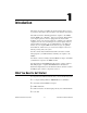
1 Introduction This chapter describes your VXI-1394 interface kit, lists what you need to get started, and includes a brief description of the hardware and software. The VXI-1394 interface kit links a PCI-based computer to the VXIbus using the IEEE 1394, or FireWire®, high-speed serial bus. This kit makes your computer perform as if it were plugged directly into the VXI backplane, giving your external computer the capability of an embedded computer.
Chapter 1 Introduction ❑ National Instruments software CD ❑ This manual VXI-1394 Interface Kit Overview The interface kit described in this manual links a 1394-equipped computer directly to the VXIbus using the IEEE 1394 bus. The VXI-1394 kit uses this high-speed (up to 400 Mbits/s) serial bus to link your computer running Windows to a VXI chassis. Note You can connect multiple 1394 devices together in a tree topology.
Chapter 1 Caution Introduction An improper Slot 0 setting may damage the VXI-1394 module and/or the VXI chassis. The VXI-1394 links the computer to the VXIbus and converts 1394 data transfers into VXIbus data transfers and vice versa. The VXI-1394 includes additional 1394 ports you can use to connect other 1394 devices. The PCI-1394 is an industry-standard 1394 host adapter on a PCI board, which gives your computer the capability to control 1394 devices.
Chapter 1 Introduction Software Description The NI-VISA/NI-VXI bus interface software includes a Resource Manager, an interactive configuration and troubleshooting program, a comprehensive library of software routines for VXI/VME programming, a logging utility you can use for debugging, and graphical interactive control programs for interacting with VISA.
Chapter 1 Introduction LabVIEW is an easy-to-use, graphical programming environment you can use to acquire data from thousands of different instruments, including IEEE 488.2 devices, VXI devices, serial devices, PLCs, and plug-in data acquisition boards. After you have acquired raw data, you can convert it into meaningful results using the powerful data analysis routines in LabVIEW.
2 Installation and Configuration This chapter explains how to set up your test system. Installing the Software Use the Setup program that came with your NI-VXI/NI-VISA software to install the entire software package or a software update, or to reinstall software in the event that your files were accidentally erased. Some of the utilities rely on the LabWindows/CVI Run-Time Engine. This software is installed, if necessary, during the NI-VXI/NI-VISA installation.
Chapter 2 Installation and Configuration Setup is an interactive, self-guiding program that installs the NI-VXI and NI-VISA software and configures your system to use the software with the VXI-1394. Complete the following steps to perform the installation. If you want to keep the manufacturer/model name tables or the VME device configuration from a previous installation, be sure to back them up before starting Setup. They are in the TBL subdirectory of your NI-VXI directory. Caution 1.
Chapter 2 Installation and Configuration Completing the Software Installation 1. Please review the information in any README files that Setup prompts you to read. 2. When the installation process completes, power off the system for the changes to take effect. If you backed up the manufacturer and model name files, restore them to the TBL subdirectory of your NI-VXI directory before running MAX.
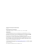
Chapter 2 Installation and Configuration To Other IEEE 1394 Devices VXI Mainframe NA IN TI ST ON RU AL ME NT IEEE 1394 Cables S ® bus VXI-1394 in Slot 0 External Computer Figure 2-1. Typical VXI-1394 System Installing Your PCI-1394 Interface Board To install the PCI-1394 interface board, complete the following steps. 1. Shut down and power off the computer. 2. Remove the computer chassis cover to expose the expansion slots and external access covers. 3.
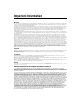
Chapter 2 5. Installation and Configuration Align the bus connector on the bottom of the host adapter with the PCI bus slot. 1 2 3 1 2 Host Adapter Mounting Bracket Host Adapter 3 Bus Contacts Figure 2-2. Installing the PCI-1394 Host Adapter 6. Carefully press the host adapter into the slot. 7. Secure the host adapter bracket to the computer chassis with the screw from the removed expansion slot cover.
Chapter 2 Installation and Configuration Installing Your VXI-1394 Interface Board All kits contain a VXI-1394 interface module. To install the VXI-1394 in Slot 0 of your VXI chassis, complete the following steps. 1. Power off the chassis. 2. Insert the VXI-1394 into the chassis in Slot 0, as shown in Figure 2-1. 3. Power on the chassis. The VXI-1394 default configuration automatically detects whether it should be the VXI system controller.
Chapter 2 Installation and Configuration Some 1394 devices require different cables than others. Your kit includes one 6-to-6-pin cable to link the VXI-1394 to your computer. Some other devices also require a 6-to-6-pin cable for proper connection to the 1394 system. Many other devices such as camcorders, VCRs, and so on, take a 6-to-4-pin cable. Powering on the System 1. Be sure all cables are connected securely. 2. Ensure that the VXI-1394 is powered on prior to starting the external computer. 3.
Developing Your Application 3 This chapter discusses the software utilities you can use to start developing applications that use NI-VXI. After installing the NI-VXI software, you can begin developing your VXI/VME application. Be sure to check the release notes for the latest application development notes and changes. NI-VXI, NI-VISA, and Related Terms Before you develop your application, it is important to understand the difference between NI-VXI, NI-VISA, and similar terms.
Chapter 3 Developing Your Application provide a high level of performance; however, there may be some slight changes in behavior for certain applications. Your software features several system development utilities including MAX, Resman, NI Spy, VISA Interactive Control (VISAIC), and VXI Interactive Control (VIC, optional). You can also access online help and a variety of examples to learn how to use NI-VXI for certain tasks.
Chapter 3 Developing Your Application Options dialog box in the Tools»NI-VXI menu, you can also use MAX to configure Resman to run on all VXI systems automatically when the computer boots. Resman reports to MAX all errors it finds in your system. When you view your VXI system in MAX, you can easily spot any errors that Resman found while configuring the system. Figure 3-1.
Chapter 3 Developing Your Application Device Interaction You can interact with your VXI/VME devices using the VISA Interactive Control (VISAIC) utility. VISAIC allows you to control your VXI/VME devices without using LabVIEW, Measurement Studio, or another programming language. You can also control your devices in MAX by right-clicking a device name and selecting Open VISA Session.
Chapter 3 Developing Your Application Open the selected resource and navigate to the Register I/O tab. In this tab, you can read registers on your device, such as the VXI device configuration registers. Execute the viIn operation (called In in LabVIEW compatibility mode) with the default parameters. The Data Value field shows the I/O operation result, such as 0x9ff6. The Return Value field shows the function status, such as 0 for VI_SUCCESS, as shown in Figure 3-3. Figure 3-3.
Chapter 3 Developing Your Application Programming for VXI NI-VISA and the NI-VXI API are the two National Instruments programming interfaces for accessing your VXI/VME instruments. With NI-VXI 3.0 or later, NI-VISA is the native API for communicating with a VXI or VME system, and NI recommends using it for all new applications. Older programs that use the NI-VXI API now use the NI-VXI-to-NI-VISA compatibility layer to communicate with the VXI devices. Using this layer, older programs can run in NI-VXI 3.
Chapter 3 Developing Your Application Table 3-1 summarizes the topics the example programs address. All files are in the VXIpnp\WinNT\NIvisa\Examples directory, in the subdirectories listed below. Table 3-1. NI-VISA/NI-VXI Examples Coverage NI-VISA Example NI-VXI Example (Optional) Message-Based Access General\RdWrt.c VXIws.c High-Level Register Access VXI-VME\HighReg.c VXIhigh.c Low-Level Register Access VXI-VME\LowReg.c VXIlow.c Sharing Memory VXI-VME\ShareSys.c VXImem.
Chapter 3 Developing Your Application Note viMemAlloc() or VXImemAlloc() returns 32-bit aligned, page-locked, continuous buffers which work efficiently with the move operations. Shared Memory In the Hardware Configuration settings for your controller in MAX, you can share memory from your computer to the VXI bus. Right-click any setting or consult the MAX online help for more information. You can access shared memory on your computer using viMemAlloc() in VISA (or VXImemAlloc() in the NI-VXI API).
Chapter 3 Developing Your Application Compatibility Layer Options Although NI-VXI supports multiple VXI controllers through NI-VISA, the NI-VXI API supports only a single controller. To specify which controller the emulation layer should use, run MAX. Select Tools»NI-VXI»VXI Options. Select the VXI system that will support the emulation layer. In NI-VXI 3.0 or later, when you enable for triggers or interrupts, only the local controller is enabled.
Chapter 3 Developing Your Application Debugging NI Spy and VISAIC are useful utilities for identifying the causes of problems in your application. NI Spy tracks the calls your application makes to National Instruments programming interfaces, including NI-VISA, NI-VXI, and NI-488. NI Spy highlights functions that return errors, so during development you can quickly spot which functions failed during a program’s execution.
Chapter 3 Developing Your Application VISAIC, discussed in the Device Interaction section, is an excellent platform for quickly testing instruments and learning how to communicate with them. Figure 3-5.
A Specifications This appendix lists the specifications for the VXI-1394 module. VXI Requirements VXIbus configuration space................... 64 B A24 or A32 space................................... Programmable Default ............................................ None Power Requirement +5 V Typical ............................................ 2.23 A Maximum (fused) ........................... 7 A –5.2 V Typical ............................................ 176 mA Maximum (fused) ......................
Appendix A Specifications I/O connectors 6-pin 1394........................................3 SMB.................................................3 GPIB (optional) ...............................1 Slot requirements ....................................Single VXI C-size slot Compatibility ..........................................Fully compatible with VXI specification VXI keying class ....................................Class 1 TTL MTBF .....................................................
Appendix A Specifications Shock and Vibration Operational shock .................................. 30 g peak, half-sine, 11 ms pulse (Tested in accordance with IEC-60068-2-27. Test profile developed in accordance with MIL-PRF-28800F.) Random vibration Operating ........................................ 5 to 500 Hz, 0.3 grms (with solid-state hard drive) Nonoperating .................................. 5 to 500 Hz, 2.4 grms (Tested in accordance with IEC-60068-2-64.
Appendix A Specifications CE Compliance This product meets the essential requirements of applicable European Directives, as amended for CE marking, as follows: Low-Voltage Directive (safety)..............73/23/EEC Electromagnetic Compatibility Directive (EMC) .....................................89/336/EEC Note Refer to the Declaration of Conformity (DoC) for this product for any additional regulatory compliance information. To obtain the DoC for this product, visit ni.
Appendix A Specifications RMW (master) VMEbus master read/modify/write transfers RMW (slave) VMEbus slave read/modify/write transfers RETRY (master) VMEbus master retry support RETRY (slave) VMEbus slave retry support FSD First slot detector SCON VMEbus System Controller (Automatic Detection) PRI, RRS Prioritized or Round Robin Select arbiter ROR, FAIR Release on Request and FAIR bus requester IH(7-1) Interrupt handler for levels 7–1 I(7-1) Interrupt requester for levels 7–1 D32, D16, D08(O) (Interrupt Ha
Appendix A Specifications LOCK Can lock the VMEbus for indivisible transfers VXI-1394 User Manual for Windows A-6 ni.
B Default Settings This appendix summarizes the default settings for the hardware and software in the VXI-1394 kit. If you need more information about a particular setting, or if you want to try a different configuration, refer to Appendix C, Advanced Hardware Configuration Settings, for your hardware reference and to the MAX online help for your software reference. Note There are no hardware settings on the PCI-1394 board. Hardware Settings Table B-1.
Appendix B Default Settings Software Settings Table B-2. MAX Device Tab Default Settings Editor Field Default Setting Logical address 0 Device class Message based Size of Servant area 0 System interrupt level Disabled Number of handlers 1 Number of interrupters 0 Table B-3.
Appendix B Default Settings Table B-4.
Advanced Hardware Configuration Settings C This appendix describes the factory-default and alternate hardware configuration settings of the VXI-1394. The board is set at the factory for the most commonly used configuration. Use this appendix if you want to try a different hardware configuration or if you would like more information on a particular setting. This information is intended for more advanced users. Hardware Default Settings The following hardware configuration settings are user configurable.
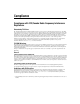
Appendix C Advanced Hardware Configuration Settings TERMINATE Y N EXT CLK10 S1 OUT IN NON INV S2 S3 SMB TRIG TERM Y N S4 CLK10 SOURCE SMB ONBRD S5 SLOT0 AUTO W1 NONSLOT0 LOAD FACTORY FACTORY USER S6 Figure C-1. VXI-1394 Default Configuration Settings VXI-1394 User Manual for Windows C-2 ni.
Appendix C Advanced Hardware Configuration Settings VXIbus Slot 0/Non-Slot 0 The VXI-1394 is configured at the factory to automatically detect if it is installed in Slot 0 of a VXIbus mainframe. With automatic Slot 0 detection, you can install the VXI-1394 into any VXIbus slot. You can manually configure the VXI-1394 for either Slot 0 or Non-Slot 0 operation by defeating the automatic-detection circuitry.
Appendix C Advanced Hardware Configuration Settings W1 Slot 0 Auto Nonslot 0 S6 Y N LOAD FACTORY A. Automatic Slot 0 Detection (Default) W1 Slot 0 Auto Nonslot 0 S6 Y N LOAD FACTORY B. Manual Slot 0 Configuration W1 Slot 0 Auto Nonslot 0 S6 Y N LOAD FACTORY C. Manual Non-Slot 0 Configuration Figure C-2. VXIbus Slot Configuration When the VXI-1394 is installed in Slot 0, it becomes the VXIbus System Controller.
Appendix C Advanced Hardware Configuration Settings As required by the VXIbus specification, the VXI-1394 drives the 10 MHz signal CLK10 on a differential ECL output when installed in Slot 0. The VXI-1394 generates a 1% accurate CLK10 signal with the onboard oscillator, or can route a 10 MHz clock from an external high-accuracy source. When not installed in Slot 0, the VXI-1394 only receives the CLK10 signal.
Appendix C Advanced Hardware Configuration Settings VXIbus CLK10 Routing When the VXI-1394 is installed in Slot 0 of your mainframe, it supplies the VXIbus CLK10 signal. The VXI-1394 has four hardware switches that work together to control various aspects of CLK10 routing. Read this section carefully and notice that if you change one switch, you may need to change another. This section includes several diagrams that show how to configure the four switches to accomplish various CLK10 configurations.
Appendix C Advanced Hardware Configuration Settings Table C-1 summarizes the most common configuration types. Table C-1.
Appendix C Advanced Hardware Configuration Settings TERMINATE Y N S1 OUT IN NON INV EXT CLK10 S2 S3 SMB TRIG TERM S4 CLK10 SOURCE SMB ONBRD S5 Figure C-4. Generate Internal CLK10 and Drive to the Backplane In Figures C-5 and C-6, switch S5 uses the alternate configuration to generate the VXIbus CLK10 signal. Instead of the onboard oscillator, the VXI-1394 generates from the external CLK SMB connector and drives to the backplane. You can choose whether to terminate the signal using S1.
Appendix C Advanced Hardware Configuration Settings TERMINATE Y N S1 OUT IN NON INV EXT CLK10 S2 S3 SMB TRIG TERM S4 CLK10 SOURCE SMB ONBRD S5 Figure C-5. Receive External CLK SMB and Drive to the Backplane Unterminated TERMINATE Y N S1 OUT IN NON INV EXT CLK10 S2 S3 SMB TRIG TERM S4 CLK10 SOURCE SMB ONBRD S5 Figure C-6.
Appendix C Advanced Hardware Configuration Settings Figures C-7 and C-8 show two configurations for driving the external CLK SMB from the VXIbus CLK10 signal by changing switch S2 to its alternate setting. Switch S5 must be in its default position for these configurations. Signal termination is not an issue when driving the signal, so the position of S1 does not matter. The difference between these two configurations is whether to use inverted or noninverted polarity when driving the signal.
Appendix C Advanced Hardware Configuration Settings TERMINATE Y N S1 OUT IN NON INV EXT CLK10 S2 S3 SMB TRIG TERM S4 CLK10 SOURCE SMB ONBRD S5 Figure C-8.
Appendix C Advanced Hardware Configuration Settings Trigger Input Termination Located within the group of CLK10 switches is switch S4, which controls whether to put a 50 Ω termination on the external trigger input SMB. Figure C-9A shows the default setting for a nonterminated trigger input SMB. Use the setting of Figure C-9B to terminate the trigger input SMB.
D Common Questions This appendix addresses common questions you may have about using the NI-VXI/NI-VISA software on the VXI-1394 platform. What does hot plugging mean in terms of IEEE 1394? The concept of hot plugging in 1394 means that you can remove and insert 1394 cables without powering down your computer and devices. The 1394 Plug and Play architecture is designed so that the host computer can recognize when to load and remove the appropriate drivers.
Appendix D Common Questions I need more devices than can fit in one chassis. How can I expand my VXI-1394 system? You can add another VXI-1394 to the system, but the additional chassis will not share the same VXI bus. The recommended strategy is to use a VXI-MXI-2, which follows the VXI-6 specification for mainframe extension. This extends full VXI functionality across multiple mainframes, including a common device address space and interframe triggering, interrupts, and bus mastering.
Appendix D Common Questions Which NI-VXI utility program must I use to configure the VXI-1394? Use MAX to configure the VXI-1394. MAX is in the National Instruments program group folder. How do I handle VME devices? Although there is no way to automatically detect VME devices in a system, you can add them easily through the Add Device Wizard in MAX.
Appendix D Common Questions What should I do if I get a Configuration EEPROM is Invalid message? There are several reasons why you might get the Configuration EEPROM is Invalid message. For example, if you turned off the VXI chassis while the configuration update process was still in progress, the board functions normally except when running MAX.
Appendix D Common Questions What is shared memory and dual-ported memory? These terms refer to a block of memory that is accessible to both a client and a server. The memory block operates as a message buffer for communications. Shared memory is applicable only if you are using either A24 or A32 address space.
Technical Support and Professional Services E Visit the following sections of the National Instruments Web site at ni.com for technical support and professional services: • Support—Online technical support resources at ni.
Appendix E Technical Support and Professional Services • Calibration Certificate—If your product supports calibration, you can obtain the calibration certificate for your product at ni.com/calibration. If you searched ni.com and could not find the answers you need, contact your local office or NI corporate headquarters. Phone numbers for our worldwide offices are listed at the front of this manual. You also can visit the Worldwide Offices section of ni.
Glossary Symbol Prefix Value p pico 10 –12 n nano 10 –9 µ micro 10 – 6 m milli 10 –3 k kilo 10 3 M mega 10 6 G giga 10 9 T tera 10 12 Symbols ° Degrees. Ω Ohms. A A Amperes. A16 space VXIbus address space equivalent to the VME 64 KB short address space. In VXI, the upper 16 KB of A16 space is allocated for use by VXI devices’ configuration registers. This 16 KB region is referred to as VXI configuration space.
Glossary address modifier One of six signals in the VMEbus specification used by VMEbus masters to indicate the address space in which a data transfer is to take place. address space A set of 2n memory locations differentiated from other such sets in VXI/VMEbus systems by six addressing lines known as address modifiers. n is the number of address lines required to uniquely specify a byte location in a given space. Valid numbers for n are 16, 24, and 32.
Glossary block-mode transfer An uninterrupted transfer of data elements in which the master sources only the first address at the beginning of the cycle. The slave is then responsible for incrementing the address on subsequent transfers so that the next element is transferred to or from the proper storage location. A VME data transfer may have no more than 256 elements. bus The group of conductors that interconnect individual circuitry in a computer.
Glossary Commander A message-based device that is also a bus master and can control one or more Servants. configuration registers A set of registers through which the system can identify a module device type, model, manufacturer, address space, and memory requirements. To support automatic system and memory configuration, the VXI specification requires that all VXIbus devices have a set of such registers. D Data Transfer Bus DTB; one of four buses on the VMEbus backplane.
Glossary EMI Electromagnetic interference. external trigger A voltage pulse from an external source that triggers an event. F fair requester A VXIbus device that will not arbitrate for the VXIbus after releasing it until it detects the bus request signal inactive. This ensures that all requesting devices will be granted use of the bus. FireWire An Apple trademark for the technology that came to be defined as IEEE 1394. See IEEE 1394. G g (1) Grams. (2) A measure of acceleration equal to 9.8 m/s2.
Glossary IDE Integrated Drive Electronics. Denotes the most common interface to the hard drive on PCs. IEC International Electrotechnical Commission. The IEC publishes internationally recognized standards. IEC 60068 contains information on environmental testing procedures and severities. IEEE Institute of Electrical and Electronics Engineers.
Glossary K K Kilo—(1) the standard metric prefix for 1,000, or 103, used with units of measure such as volts, hertz, and meters; (2) the prefix for 1,024, or 210, used with B (byte) in quantifying data or computer memory. L logical address An 8-bit number that uniquely identifies each VXIbus device in a system. It defines the A16 register address of a device, and indicates Commander and Servant relationships. M m Meters.
Glossary NI-VXI The National Instruments bus interface software for VME/VXIbus systems. Non-Slot 0 device A device configured for installation in any slot in a VXIbus mainframe other than Slot 0. Installing such a device into Slot 0 can damage the device, the VXIbus backplane, or both. O OHCI Open Host Controller Interface. Specification for the register set for a 1394 controller card. This standard allows interoperability of software with controllers from different vendors.
Glossary S s Seconds. SIMM Single In-line Memory Module. slave A functional part of a VME/VXIbus device that detects data transfer cycles initiated by a VMEbus master and responds to the transfers when the address specifies one of the device’s registers. Slot 0 device A device configured for installation in Slot 0 of a VXIbus mainframe.
Glossary VIC VXI Interactive Control program, a part of the NI-VXI bus interface software. Used to program VXI devices and develop and debug VXI application programs. VISA Virtual Instrument Software Architecture. This is the general name given to VISA and its associated architecture. VISAIC VISA Interactive Control program, a part of the NI-VISA software. Used to program devices and develop and debug application programs. VITA VMEbus International Trade Association.
Index Numerics serial number and hardware revision of VXI-1394, D-2 shared memory and dual-ported memory, D-5 VME devices, D-3 VXI-1394 system expansion, D-2 compatibility layer options, 3-9 compiler symbols, 3-8 configuration, 2-1, 3-2 advanced hardware settings, C-1 advanced options, 1-3, C-1 default settings, B-1 EEPROM, C-5 hardware, 2-3 setup, 2-1 VXI-1394 default configuration settings (figure), C-2 VXIbus slot configuration (figure), C-4 Configuration EEPROM is Invalid message, D-4 connectors, 1394
Index I NI resources, E-1 related documentation, ix drivers (NI resources), E-1 IEEE 1394, capability descriptions, A-4 installation, 2-1 instrument drivers (NI resources), E-1 E K EEPROM configuration, C-5 Configuration EEPROM is Invalid message, D-4 operation (figure), C-5 electromagnetic compatibility, A-3 electrostatic discharge (caution), 2-3 example programs (table), 3-7 examples (NI resources), E-1 KnowledgeBase, E-1 L LabVIEW, 1-5 LabWindows/CVI, 1-5 LEDs 1394, 1-3 definitions of, D-4 SYSFAIL
Index S NI support and services, E-1 NI-VISA definition, 3-1 installing, 2-1 NI-VISA/NI-VXI software example programs (table), 3-7 NI-VXI definition, 3-1 installing, 2-1 NI-VXI API, 3-8 compatibility layer options, 3-9 compiler symbols, 3-8 definition, 3-1 NI-VXI compatibility layer, 3-1 safety specifications (table), A-3 setup, 2-1 shared memory, 3-8 shared memory tab default settings (table), B-2 shock and vibration specifications, A-3 slot 0/non-slot 0, C-3 slot configuration, VXI bus (figure), C-4 so
Index V interface kit overview, 1-2 module description, 1-2 specifications, A-1 system expansion, D-2 typical system setup (figure), 2-4 VXIbus CLK10 routing, C-6 slot 0/non-slot 0, C-3 slot configuration (figure), C-4 VXIbus transfers, optimizing, 3-7 viIn access in VISAIC (figure), 3-5 VISAIC figure, 3-11 selecting a controller in (figure), 3-4 VMEbus capability codes, A-4 VXI bus tab default settings (table), B-3 VXI LED, 1-3 VXI, programming, 3-6 VXI-1394 default configuration settings (figure), C-2