USER GUIDE NI USB-622x/625x/628x OEM M Series USB-6221/6225/6229/6251/6255/6259/6281/6289 OEM Devices This document provides dimensions, pinouts, and information about the connectors, switch, LEDs, and chassis ground of the National Instruments USB-6221 OEM, USB-6225 OEM, USB-6229 OEM, USB-6251 OEM, USB-6255 OEM, USB-6259 OEM, USB-6281 OEM, and USB-6289 OEM devices. It also explains how to modify the USB device name in Microsoft Windows.
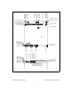
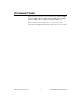
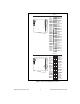
Refer to the NI 622x Specifications document for USB-6221/6225/6229 specifications, the NI 625x Specifications document for USB-6251/6255/6259 specifications, and the NI 628x Specifications document for USB-6281/6289 specifications. Refer to the M Series User Manual for more information about USB-622x/625x/628x devices. You can find all documentation at ni.com/manuals. Dimensions Figure 2 shows the dimensions of the USB-6221/6251/6281 OEM device. NI USB-622x/625x/628x OEM User Guide 2 ni.
5.900 (149.86) 6.013 (152.74) 6.400 (162.56) 5.210 (132.33) 3.198 (81.22) 3.220 (81.79) 3.730 (94.74) 3.734 (94.84) 3.180 (80.77) 0.000 (0.00) 0.200 (5.08) 0.390 (9.91) 0.918 (23.32) 6.950 (176.53) 4x 6.718 (170.63) 6.270 (159.26) 6.140 (155.96) 5.930 (150.62) 4X Ø 0.110 (2.79) 7X Ø 0.125 (3.18) 6.140 (155.96) 5.290 (134.37) 0.396 (10.06) 0.304 (7.72) 0.256 (6.50) 0.116 (2.95) 0.000 (0.00) 6.200 (157.48) 3.296 (83.72) 3.080 (78.23) 2.072 (52.63) 2.300 (58.42) 2.606 (66.19) 1.750 (44.45) 0.436 (11.
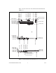
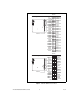
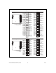
5.900 (149.86) 6.013 (152.74) 6.400 (162.56) 5.210 (132.33) 3.198 (81.22) 3.220 (81.79) 3.730 (94.74) 3.734 (94.84) 3.180 (80.77) 0.000 (0.00) 0.200 (5.08) 0.390 (9.91) 0.918 (23.32) Figure 3 shows the dimensions of the USB-6225/6229/6255/6259/6289 OEM device. 6.950 (176.53) 4x 6.718 (170.63) 6.270 (159.26) 6.140 (155.96) 5.930 (150.62) 5.839 (148.31) 5.499 (139.67) 4X Ø 0.110 (2.79) 7X Ø 0.125 (3.18) 6.140 (155.96) 5.290 (134.37) 0.396 (10.06) 0.304 (7.72) 0.256 (6.50) 0.116 (2.95) 0.000 (0.00) 6.
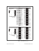
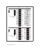
I/O Connector Pinouts Figures 4 through 9 show the connector pinouts for the USB-6221 OEM, USB-6225 OEM, USB-6229 OEM, USB-6251 OEM, USB-6255 OEM, USB-6259 OEM, USB-6281 OEM, and USB-6289 OEM devices. Refer to the M Series User Manual at ni.com/manuals for more information about USB-622x/625x/628x signals and how to connect them.
Bank 0 50-Pin Digital Connector Bank 0 +5 V D GND D GND D GND D GND D GND D GND D GND D GND D GND D GND D GND D GND D GND D GND D GND D GND D GND D GND D GND D GND D GND D GND D GND D GND 50 48 46 44 42 40 38 36 34 32 30 28 26 24 22 20 18 16 14 12 10 8 6 4 2 49 47 45 43 41 39 37 35 33 31 29 27 25 23 21 19 17 15 13 11 9 7 5 3 1 +5 V PFI 15 PFI 14 PFI 13 PFI 12 PFI 11 PFI 10 PFI 9 PFI 8 PFI 7 PFI 6 PFI 5 PFI 4 PFI 3 PFI 2 PFI 1 PFI 0 P0.7 P0.6 P0.5 P0.4 P0.3 P0.2 P0.1 P0.
Bank 0 Bank 1 50-Pin Analog/Digital Connectors Bank 1 Bank 0 +5 V D GND D GND D GND D GND D GND D GND D GND D GND D GND D GND D GND D GND D GND D GND D GND D GND D GND D GND D GND D GND D GND D GND D GND D GND 50 48 46 44 42 40 38 36 34 32 30 28 26 24 22 20 18 16 14 12 10 8 6 4 2 49 47 45 43 41 39 37 35 33 31 29 27 25 23 21 19 17 15 13 11 9 7 5 3 1 +5 V PFI 15 PFI 14 PFI 13 PFI 12 PFI 11 PFI 10 PFI 9 PFI 8 PFI 7 PFI 6 PFI 5 PFI 4 PFI 3 PFI 2 PFI 1 PFI 0 P0.7 P0.6 P0.5 P0.4 P0.3 P0.2 P0.1 P0.
Bank 1 50-Pin Digital Connectors Bank 1 Bank 0 50 48 46 44 42 40 38 36 34 32 30 28 26 24 22 20 18 16 14 12 10 8 6 4 2 +5 V D GND D GND D GND D GND D GND D GND D GND D GND D GND D GND D GND D GND D GND D GND D GND D GND D GND D GND D GND D GND D GND D GND D GND D GND 49 47 45 43 41 39 37 35 33 31 29 27 25 23 21 19 17 15 13 11 9 7 5 3 1 Bank 0 +5 V P0.31 P0.30 P0.29 P0.28 P0.27 P0.26 P0.25 P0.24 P0.23 P0.22 P0.21 P0.20 P0.19 P0.18 P0.17 P0.16 P0.15 P0.14 P0.13 P0.12 P0.11 P0.10 P0.9 P0.
Bank 0 50-Pin Digital Connector Bank 0 +5 V D GND D GND D GND D GND D GND D GND D GND D GND D GND D GND D GND D GND D GND D GND D GND D GND D GND D GND D GND D GND D GND D GND D GND D GND 50 48 46 44 42 40 38 36 34 32 30 28 26 24 22 20 18 16 14 12 10 8 6 4 2 49 47 45 43 41 39 37 35 33 31 29 27 25 23 21 19 17 15 13 11 9 7 5 3 1 +5 V PFI 15 PFI 14 PFI 13 PFI 12 PFI 11 PFI 10 PFI 9 PFI 8 PFI 7 PFI 6 PFI 5 PFI 4 PFI 3 PFI 2 PFI 1 PFI 0 P0.7 P0.6 P0.5 P0.4 P0.3 P0.2 P0.1 P0.
Bank 0 Bank 1 50-Pin Analog/Digital Connectors Bank 1 Bank 0 +5 V D GND D GND D GND D GND D GND D GND D GND D GND D GND D GND D GND D GND D GND D GND D GND D GND D GND D GND D GND D GND D GND D GND D GND D GND 50 48 46 44 42 40 38 36 34 32 30 28 26 24 22 20 18 16 14 12 10 8 6 4 2 49 47 45 43 41 39 37 35 33 31 29 27 25 23 21 19 17 15 13 11 9 7 5 3 1 +5 V PFI 15 PFI 14 PFI 13 PFI 12 PFI 11 PFI 10 PFI 9 PFI 8 PFI 7 PFI 6 PFI 5 PFI 4 PFI 3 PFI 2 PFI 1 PFI 0 P0.7 P0.6 P0.5 P0.4 P0.3 P0.2 P0.1 P0.
Bank 0 Bank 1 50-Pin Digital Connectors Bank 1 Bank 0 +5 V D GND D GND D GND D GND D GND D GND D GND D GND D GND D GND D GND D GND D GND D GND D GND D GND D GND D GND D GND D GND D GND D GND D GND D GND 50 48 46 44 42 40 38 36 34 32 30 28 26 24 22 20 18 16 14 12 10 8 6 4 2 49 47 45 43 41 39 37 35 33 31 29 27 25 23 21 19 17 15 13 11 9 7 5 3 1 +5 V P0.31 P0.30 P0.29 P0.28 P0.27 P0.26 P0.25 P0.24 P0.23 P0.22 P0.21 P0.20 P0.19 P0.18 P0.17 P0.16 P0.15 P0.14 P0.13 P0.12 P0.11 P0.10 P0.9 P0.
Default Counter/Timer Pinouts By default, NI-DAQmx routes the counter/timer inputs and outputs to the PFI pins, shown in Table 1. Table 1.
Attaching External LEDs USB-622x/625x/628x OEM devices have two LEDs that reflect the device state. The green READY LED indicates when the device is powered on and configured as a USB device. The yellow ACTIVE LED indicates USB bus activity. Three connectors on the device allow you to connect an external LED circuit to the device, as shown in Figure 10. To connect an external READY LED, use E1 as the positive connection (+3.3 V) and E2 as the negative connection.
Power Switch The power switch on the USB-622x/625x/628x OEM device powers the device on and off. Figure 11 shows the pins on the power switch and circuitry. 100 kΩ to Ground VDC Out 3 1 XF1 100 kΩ 2 VDC In SW1 Switch NC J4/J6/J8 NC Outer Shell SW1 Power to Device 2 1 3 XF1 FUSE J4/J6/J8 Power Connector 100 kΩ Figure 11. Schematic for the Power Switch Pin 1, VDC In, is connected to VDC through the fuse (reference designator XF1).
Connecting the USB-622x/625x/628x OEM Device to Your Chassis The USB-622x/625x/628x OEM device includes several plated mounting holes that are designed for customer grounded connections, as shown in Figure 12. Caution Do not use the holes labeled A in Figure 12 as mounting holes. A A A Mounting Hole Connected to Chassis Ground A Do Not Use These as Mounting Holes Figure 12.
Replacing Fuses USB-622x/625x/628x OEM devices have a replaceable T 2A 250V (5 × 20 mm) fuse that protects the device from overcurrent through the power connector. (USB-628x Devices Only) USB-628x OEM devices also have a replaceable F 2A 125V fuse that protects the device from overcurrent through the +5 V terminal(s). Replacement fuse information can be found in Table 2. To replace a broken fuse in USB-622x/625x/628x OEM devices, complete the following steps. 1. Power down and unplug the device. 2.
Device Components Table 2 contains information about the components used for interfacing and interacting with the USB-622x/625x/628x OEM device. Table 2.
Modifying the USB Device Name in Microsoft Windows You can change how the USB-622x/625x/628x OEM device name appears when users install the device in both the Found New Hardware Wizard that appears when the device is initially installed and in the Windows Device Manager. Windows Vista/XP Users Figure 14 depicts how a USB-6251 OEM device name appears in the Found New Hardware Wizard and Windows Device Manager. Figure 14.
New security updates to Microsoft Vista and NI-DAQ 8.6 or later create random INF files for NI hardware. Windows assigns random file numbers to all INF files, which causes the user to search through several INF files until the correct file is located. Note If you want to revert back, save a copy of this file as OEMx_original.inf in a different location. 2. Edit the device INF file by opening OEMx.inf with a text editor.
When you reconnect and power on the device, it appears as My Device in the Found New Hardware Wizard and Windows Device Manager, as shown in Figure 16. When the device is initially installed, the Windows alert message may display the following: Found New Hardware: M Series USB 62xx (OEM). This message appears for a few seconds until the custom name appears and the Found New Hardware Wizard is launched. This alert message device name cannot be changed. Note Figure 16.
Windows 2000 Users Figure 17 depicts how a USB-6251 OEM device name appears in the Found New Hardware Wizard and Windows Device Manager. Figure 17. USB-6251 OEM Device in the Found New Hardware Wizard and Device Manager (Windows 2000) To modify the device name in the Found New Hardware Wizard and Windows Device Manager in Windows 2000, complete the following steps. Note You must have NI-DAQmx 8.7 or later installed on your PC. 1. Locate the nimioxsu.
2. Edit the device INF file by opening nimioxsu.inf with a text editor. At the bottom of this file are the descriptors where Windows looks to identify the device. Locate the two lines of text that contain in quotes the descriptors for the device name you are modifying. Change the descriptor on both lines to the new device name, as shown in Figure 18. Original File Modified File Figure 18. INF File Descriptors Changed to “My Device” (Windows 2000) 3. Save and close the INF file. 4.
When you reconnect and power on the device, it appears as My Device in the Found New Hardware Wizard and Windows Device Manager, as shown in Figure 19. When the device is initially installed, the Windows alert message may display the following: Found New Hardware: M Series USB 62xx (OEM). This message appears for a few seconds until the custom name appears and the Found New Hardware Wizard is launched. This alert message device name cannot be changed. Note Figure 19.