PXI NI PXI-8183 User Manual NI PXI-8183 User Manual October 2008 372512B-01
Support Worldwide Technical Support and Product Information ni.
Important Information Warranty The NI PXI-8183 is warranted against defects in materials and workmanship for a period of one year from the date of shipment, as evidenced by receipts or other documentation. National Instruments will, at its option, repair or replace equipment that proves to be defective during the warranty period. This warranty includes parts and labor.
Contents About This Manual How to Use the Documentation Set...............................................................................vii Conventions ...................................................................................................................vii Related Documentation..................................................................................................viii Chapter 1 Introduction Benefits of PXI ...........................................................................
Contents Chapter 3 I/O Information Front Panel Connectors ................................................................................................. 3-1 Front Panel..................................................................................................................... 3-2 VGA ................................................................................................................ 3-3 COM1.............................................................................................
About This Manual This manual contains detailed instructions for installing and configuring your National Instruments NI PXI-8183 embedded computer kit. How to Use the Documentation Set Begin by reading the NI PXI-8183 Installation Guide, a brief quick-start guide that describes how to install and get started with your controller. This manual contains more details about changing the installation or configuration from the defaults and using the hardware.
About This Manual monospace bold Bold text in this font denotes the messages and responses that the computer automatically prints to the screen. This font also emphasizes lines of code that are different from the other examples. Related Documentation The following documents contain information you may find helpful as you read this manual: NI PXI-8183 User Manual • PICMG 2.0 R3.0 CompactPCI Specification, PCI Industrial Computers Manufacturers Group • IEEE Standard P1284.
1 Introduction Benefits of PXI The PXIbus specification defines a compact modular PC platform for industrial instrumentation. PXI leverages the PCI bus, which is the de facto standard for today’s desktop computer software and hardware designs. As a result, PXI users receive all the benefits of PCI within an architecture that supports mechanical, electrical, and software features tailored to industrial instrumentation, data acquisition, and automation applications.
Chapter 1 Introduction NI PXI-8183 Description The NI PXI-8183 PXI/CompactPCI embedded computer is a high-performance PXI/CompactPCI-compatible system controller. The NI PXI-8183 controller integrates standard I/O features in a single unit by using state-of-the-art packaging. Combining a NI PXI-8183 embedded controller with a PXI-compatible chassis, such as the PXI-1036, results in a fully PC-compatible computer in a compact, rugged package.
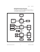
Chapter 1 Introduction NI PXI-8183 Functional Description The NI PXI-8183 is a modular PC in a PXI 3U-size form factor. Figure 1-1 is a functional block diagram of the NI PXI-8183. Following the diagram is a description of each logic block shown.
Chapter 1 Introduction The NI PXI-8183 consists of the following logic blocks on the CPU module: • The Socket 370 CPU is the socket definition for the Intel Pentium III processor families. • The SO-DIMM block consists of a 64-bit SDRAM socket that can hold up to 512 MB. • The Chip Set GMCH connects to the CPU, SDRAM, and video. • The SMB to PXI Trigger provides a routable connection of the PXI triggers to/from the SMB on the front panel.
Chapter 1 Introduction digital I/O, counter/timer operations, SCXI, RTSI, self-calibration, messaging, and acquiring data to extended memory. NI-VISA is the National Instruments implementation of the VISA specification. VISA is a uniform API for communicating and controlling Serial, GPIB, PXI, VXI, and various other types of instruments. This API aids in the creation of more portable applications and instrument drivers.
Installation and Configuration 2 This chapter contains information about installing and configuring your NI PXI-8183 controller. Installing the NI PXI-8183 This section contains general installation instructions for the NI PXI-8183. Consult your PXI chassis user manual for specific instructions and warnings. 1. Plug in your chassis before installing the NI PXI-8183. The power cord grounds the chassis and protects it from electrical damage while you install the module.
Chapter 2 Installation and Configuration 4. Remove the protective plastic covers from the four bracket-retaining screws as shown in Figure 2-1. 1 1 Protective Screw Cap (4X) Figure 2-1. Removing Protective Screw Caps Caution Do not raise the injector/ejector handle as you insert the NI PXI-8183. The module will not insert properly unless the handle is in its downward position so that it does not interfere with the injector rail on the chassis. NI PXI-8183 User Manual 5.
Chapter 2 9. Installation and Configuration Check the installation. 10. Connect the keyboard and mouse to the appropriate connectors. If you are using a PS/2 keyboard and a PS/2 mouse, use the Y-splitter adapter (refer to Figure 4-1, Y-Splitter Cable) included with your controller to connect both to the PS/2 connector. 11. Connect the VGA monitor video cable to the VGA connector. 12. Connect devices to ports as required by your system configuration. 13. Power on the chassis. 14.
Chapter 2 Installation and Configuration How to Remove the Controller from the PXI Chassis The NI PXI-8183 controllers are designed for easy handling. To remove the unit from the PXI chassis, complete the following steps: 1. Power off the chassis. 2. Remove the bracket-retaining screws in the front panel. 3. Press the injector/ejector handle down. 4. Slide the unit out of the chassis. BIOS Setup You can change the NI PXI-8183 configuration settings in the BIOS setup.
Chapter 2 Installation and Configuration • Up Arrow, Down Arrow—Use these keys to move between the options within a setup menu. (To use the arrows on the numeric keypad, you must turn off Num Lock.) • —Use this key either to enter a submenu or display all available settings for a highlighted configuration option. • —Use this key to return the parent menu of a submenu. At the top-level menus, this key serves as a shortcut to the Exit menu.
Chapter 2 Installation and Configuration DMI Event Logging Submenu Major errors that occur during the BIOS booting process are stored in battery-backed memory on the controller, and remain there until you view and clear them using this submenu. This logging capability allows a system administrator to detect the historical occurrence of faults on a controller.
Chapter 2 Installation and Configuration • Local Bus IDE Adapter—The NI PXI-8183 controller has two integrated IDE/ATA channels (Primary and Secondary), each capable of supporting two ATA devices (Master and Slave). Use this setting to disable one or more of these integrated channels. You should modify this setting only if specified in other sections of this manual. The default is Both.
Chapter 2 Installation and Configuration • Floppy Drive—You can route the internal signals used for the 3.5 in. floppy drive operation through the pins on the parallel port connector. Use this setting to operate the NI PXI-8183 controller with a specialized external floppy drive. Normally, using a Universal Serial Bus (USB) floppy drive is preferable to this option, which requires a specially designed drive and cable.
Chapter 2 Installation and Configuration LabVIEW RT Setup Menu Note This menu is visible only if the controller supports LabVIEW RT. Use this menu to configure boot options for LabVIEW RT if it is installed on the controller. If you are not using LabVIEW RT, you should leave these settings as default. Note These settings override the behavior of the switches on SW1. Refer to the LabVIEW RT Configuration Switches section for more information.
Chapter 2 Installation and Configuration BIOS setup using the user password, the only BIOS setting you can modify is the user password. The default is no password. • Password on Boot—This setting controls whether the controller requires a supervisor or user password to boot an operating system. If you enter the supervisor password on boot, you have supervisor-level diskette access. If you enter the user password on boot, you have user-level diskette access.
Chapter 2 Installation and Configuration Exiting BIOS Setup The Exit setup menu includes all available options for exiting, saving, and loading the BIOS default configuration. As an alternative to this screen, press to load BIOS default settings and to save changes and exit setup. The Exit setup menu includes the following settings: • Exit Saving Changes—Any changes made to BIOS settings are stored in the battery-backed System CMOS. The setup program then exits and reboots the controller.
Chapter 2 Installation and Configuration System CMOS The NI PXI-8183 contains a backed-up memory used to store BIOS configuration information. Complete the following steps to clear the CMOS contents: Caution 1. Power off the chassis. 2. Remove the controller from the chassis. 3. Move the jumper on J1 from pins 1–2 to pins 2–3, as shown in Figure 2-3. Do not leave the jumper on pins 2–3. Doing so decreases battery life. 4. Wait one second. Move the jumper back to pins 1–2. 5.
Chapter 2 Installation and Configuration LabVIEW RT Configuration Switches Note These switches are functional only if the controller supports LabVIEW RT. Use the LabVIEW RT configuration switches to configure LabVIEW RT if it is installed on the controller. If you are not using LabVIEW RT, these switches should remain in the OFF position. The controller reads these switches only after a system reset. You must reboot the controller for any changes to take place.
Chapter 2 Installation and Configuration Figure 2-4 shows the location of the LabVIEW RT configuration switches. The switches are shown in the OFF position. 4 3 1 1 2 Switch 1—Reset IP Address Switch 2—Disable Startup VI 3 4 2 Switch 3—Boot Safe Mode Switch 4—Boot LabVIEW RT Figure 2-4. LabVIEW RT Configuration Switches NI PXI-8183 User Manual 2-14 ni.
Chapter 2 Installation and Configuration Drivers and Software Files and Directories Installed on Your Hard Drive Your hard drive includes a directory called images in its root that contains software and soft copies of manuals for the peripherals. The directory structure under the images directory is logically organized into several levels. In the images directory, you will find a manuals directory, an os directory, and directories for each computer peripheral.
Chapter 2 Installation and Configuration Upgrading RAM You can change the amount of installed RAM on the NI PXI-8183 by upgrading the SO-DIMM. To upgrade the RAM, remove the NI PXI-8183 from the PXI chassis. Remove the old SO-DIMM module and install the new SO-DIMM in the socket as shown in Figure 2-5. National Instruments offers the following types of SO-DIMMs for use with the NI PXI-8183 controller. • 256 MB, 32 MB × 64, 7.5 ns, 1.05 in. max • 512 MB, 64 MB × 64, 7.5 ns, 1.05 in.
Chapter 2 Installation and Configuration Hard Drive Recovery NI PXI-8183 controllers include Phoenix Technologies Ltd. Firstware tools, either Recover or Vault, or both. These tools allow you to recover the original factory condition of the hard disk from a small protected area of your hard drive. This protected area contains an image of the hard disk provided to you at the time of shipment.
Chapter 2 Installation and Configuration Installing from a Network Complete the following steps to install an OS from a network: 1. Create a network bootdisk. (Refer to the readme.txt file in the netboot folder on your OS installation CD.) 2. Use another PC on the network with a CD-ROM drive. Share the drive and load the OS installation CD. 3. Boot your NI PXI-8183 using the network boot disk. 4. Run the net utility from the a: drive. Map the shared CD-ROM (for example, drive z:). 5. Run winnt.
3 I/O Information Front Panel Connectors Table 3-1 lists various peripherals and their corresponding NI PXI-8183 external connectors, bus interfaces, and functions. Table 3-1.
Chapter 3 I/O Information Front Panel .00 [0] 0.34 [8.7] 0.86 [21.9] 1.20 [30.4] 0.95 [24.2] Figure 3-1 shows the front panel layout and dimensions of the NI PXI-8183. Dimensions are in inches [millimeters]. .00 [0] .68 [17.1] 1.25 [31.8] 1.52 [38.5] 1.85 [47.1] 2.49 [63.3] 3.00 [76.3] 3.46 [87.9] 0.34 [8.7] 0.94 [23.9] 0.97 [24.6] NI PXI-8183 Embedded Controller Figure 3-1. NI PXI-8183 Front Panel Layout and Dimensions NI PXI-8183 User Manual 3-2 ni.
Chapter 3 I/O Information VGA Figure 3-2 shows the location and pinouts for the VGA connector on the NI PXI-8183. Table 3-2 lists and describes the VGA connector signals. AMP manufactures a mating connector with part numbers 748364-1 (housing) and 748333-2 (pin contact). 11 6 1 VGA 15 10 5 NI PXI-8183 Embedded Controller Figure 3-2. VGA Connector Location and Pinout Table 3-2.
Chapter 3 I/O Information Table 3-2. VGA Connector Signals (Continued) Pin Signal Name Signal Description 11 NC Not Connected 12 SD Serial Data 13 HSync Horizontal Sync 14 VSync Vertical Sync 15 SC Serial Clock COM1 Figure 3-3 shows the location and pinouts for the COM1 connector on the NI PXI-8183. Table 3-3 lists and describes the COM1 connector signal. AMP manufactures a serial port mating connector, part number 745491-5.
Chapter 3 I/O Information Table 3-3. COM1 Connector Signals (Continued) Pin Signal Name Signal Description 5 GND Ground 6 DSR* Data Set Ready 7 RTS* Ready to Send 8 CTS* Clear to Send 9 RI* Ring Indicator Ethernet Figure 3-4 shows the location and pinouts for the Ethernet connector on the NI PXI-8183. Table 3-4 lists and describes the Ethernet connector signals. AMP manufactures a mating connector, part number 554739-1. 1 Ethernet 8 NI PXI-8183 Embedded Controller Figure 3-4.
Chapter 3 I/O Information Table 3-4. Ethernet Connector Signals (Continued) Pin Signal Description 5 NC 6 Differential Receive 7 NC 8 NC Parallel Port Figure 3-5 shows the location and pinouts for the IEEE 1284 (parallel) connector on the NI PXI-8183. Table 3-5 lists and describes the IEEE 1284 connector signals. Parallel port adapter cables are available from National Instruments, part number 777169-01. 1 19 Parallel Port 18 36 NI PXI-8183 Embedded Controller Figure 3-5.
Chapter 3 I/O Information Table 3-5.
Chapter 3 I/O Information Universal Serial Bus Figure 3-6 shows the location and pinouts for the Universal Serial Bus (USB) connector on the NI PXI-8183. Table 3-6 lists and describes the USB connector signals. AMP manufactures a USB mating connector, part number 787633. 4 1 USB NI PXI-8183 Embedded Controller Figure 3-6. USB Connector Location and Pinout Table 3-6.
Chapter 3 I/O Information PS/2 Figure 3-7 shows the location and pinouts for the PS/2 connector on the NI PXI-8183. Table 3-7 lists and describes the PS/2 connector signals. To connect both a PS/2 keyboard and PS/2 mouse to the NI PXI-8183, use the Y-splitter adapter cable included with your controller (refer to Figure 4-1, Y-Splitter Cable). Replacement Y-splitter cables are available from National Instruments, part number 778713-01. 5 3 1 2 PS/2 6 4 NI PXI-8183 Embedded Controller Figure 3-7.
Chapter 3 I/O Information Trigger The TRG connector is the software-controlled trigger connection for routing PXI triggers to or from the backplane trigger bus. Figure 3-8 shows the TRG connector location on the NI PXI-8183. Table 3-8 lists and describes the trigger connector signals. 2 1 NI PXI-8183 Embedded Controller Figure 3-8. TRG Connector Location and Pinout Table 3-8.
Chapter 3 I/O Information Front Panel Features The NI PXI-8183 have the following front-panel features: • A system reset pushbutton (hold the button for at least two seconds to generate a reset to the controller). • Two front-panel LEDs that show PC status. – The POWER OK LED indicates that the power is on and reset is no longer asserted. – The DRIVE LED indicates when an access to the internal hard disk is occurring.
4 Common Configuration Questions This chapter answers common configuration questions you may have when using the NI PXI-8183 embedded controller. General Questions What do the LEDs on the NI PXI-8183 front panel mean? The green LED indicates the power supplies to/on the NI PXI-8183 are within spec. The supplies monitored are 3.3 V, 5 V, +12 V, and the internally regulated processor core voltage. The hard drive LED lights when there is hard drive activity on the NI PXI-8183.
Chapter 4 Common Configuration Questions Boot Options What devices can I boot from? The NI PXI-8183 can boot from the following devices: • The internal IDE hard drive • An external SCSI hard drive or CD-ROM if an SCSI adapter, such as the PXI-8214, is used • An external USB mass storage device such as a USB hard drive or CD-ROM • An external USB floppy drive Note There are some limitations when booting from a USB device.
Chapter 4 Common Configuration Questions Cables and Connections How do I plug both a PS/2 mouse and PS/2 keyboard into the controller? The NI PXI-8183 has a combined PS/2 mouse and PS/2 keyboard connector, so you need to use the PS/2 Y-splitter cable shipped with the NI PXI-8183, shown in Figure 4-1, to connect both a PS/2 mouse and PS/2 keyboard. Figure 4-1.
Chapter 4 Common Configuration Questions Operating System and Software Driver Installation How do I install or reinstall the video driver? Refer to the Drivers.txt file on the hard drive or recovery CD-ROM. How do I install or reinstall the Ethernet driver? Refer to the Drivers.txt file on the hard drive or recovery CD-ROM. How do I install software from a CD? The compact size of the NI PXI-8183 does not allow for an integrated CD-ROM drive.
Chapter 4 Common Configuration Questions Chassis Configuration How do I set up the NI PXI-8183 to work with my chassis? Configuration of the PXI system is handled through Measurement & Automation Explorer (MAX), included with the software pre-installed on your controller. MAX creates the pxisys.ini file, which defines the layout and parameters of your PXI system. The configuration steps for single or multiple-chassis systems are the same. Figure 4-2.
Chapter 4 Common Configuration Questions Basic PXI System Configuration 1. Launch MAX. 2. In the Configuration tree, click the Devices and Interfaces branch to expand it. 3. If the PXI system controller has not yet been configured, it is labeled PXI System (Unidentified). Right-click this entry to display the pop-up menu, then select the appropriate controller model from the Identify As submenu. 4. Click the PXI System controller.
Chapter 4 Common Configuration Questions Upgrade Information How do I upgrade system memory? You can change the amount of installed RAM on the NI PXI-8183 by upgrading the SO-DIMM. To upgrade the RAM, remove the NI PXI-8183 from the PXI chassis. Remove the old SO-DIMM module and install the new SO-DIMM in the socket as shown in Figure 4-3. National Instruments offers the following types of SO-DIMMs for use with the NI PXI-8183 controller. • 256 MB, 32 MB × 64, 7.5 ns, 1.05 in.
Chapter 4 Common Configuration Questions How do I flash a new BIOS? For information on updating the BIOS, refer to KnowledgeBase 2GIGKD0Z at ni.com/support. Where do I get the latest software drivers? You can download the latest drivers from ni.com/support/ pxisupp.htm. My NI PXI-8183 does not have an internal floppy drive. Is there a way to use an external drive? Yes. The NI PXI-8183 controllers support and can boot from USB floppy drives. Refer to the Boot Options section for more information.
5 Troubleshooting This chapter answers common troubleshooting questions you may have when using the NI PXI-8183 embedded computer. What if the NI PXI-8183 does not boot? Several problems can cause a controller not to boot. Here are some things to look for and possible solutions. Things to Notice • Which LEDs come on? The Power OK LED should stay lit. The Drive LED should blink during boot as the disk is accessed.
Chapter 5 Troubleshooting My controller boots fine until I get to Windows, at which point I cannot read the screen. This may include garbled output, white screen, black screen, or an out of sync message from the monitor. This problem usually results from having the video card output set past the limits of the monitor. You will need to boot Windows in Safe Mode. To do this, reboot the controller. As Windows begins to boot, hold down . You should now be able to reset the video driver to lower settings.
A Specifications This appendix lists the electrical, mechanical, and environmental specifications of the NI PXI-8183 embedded computers. Electrical Current (A) Voltage (V) Typical Maximum +3.3 3.0 A 4.0 A +5 4.5 A 6.0 A +12 0.01 A 0.04 A –12 0A 0.0 A Physical Board dimensions................................... PXI 3U-size module 8.1 × 13 × 21.6 cm (3.2 × 5.1 × 8.5 in.) Slot requirements ................................... One system slot plus one controller expansion slot Compatibility ...
Appendix A Specifications Operating Environment Ambient temperature range1 ...................5 °C to 50 °C2, 3 (Tested in accordance with IEC-60068-2-1 and IEC-60068-2-2.) Relative humidity range..........................10% to 90%, noncondensing (Tested in accordance with IEC-60068-2-56.) Altitude ...................................................2,000 m (at 25 °C ambient temperature) Pollution Degree .....................................2 For indoor use only.
Appendix A Specifications Random vibration Operating ........................................ 5 to 500 Hz, 0.3 grms (with solid-state hard drive) Nonoperating .................................. 5 to 500 Hz, 2.4 grms (Tested in accordance with IEC-60068-2-64. Nonoperating test profile exceeds the requirements of MIL-PRF-28800F, Class B.) Note Specifications are subject to change without notice.
Appendix A Specifications CE Compliance This product meets the essential requirements of applicable European Directives as follows: • 2006/95/EC; Low-Voltage Directive (safety) • 2004/108/EC; Electromagnetic Compatibility Directive (EMC) Online Product Certification Refer to the product Declaration of Conformity (DoC) for additional regulatory compliance information. To obtain product certifications and the DoC for this product, visit ni.
Appendix A Specifications Battery Replacement and Disposal This device contains a long-life coin cell battery. If you need to replace it, use the Return Material Authorization (RMA) process or contact an authorized National Instruments service representative. After replacement, recycle the old battery. For additional information, visit ni.com/environment.
Technical Support and Professional Services B Visit the following sections of the award-winning National Instruments Web site at ni.com for technical support and professional services: • Support—Technical support at ni.com/support includes the following resources: – Self-Help Technical Resources—For answers and solutions, visit ni.
Appendix B Technical Support and Professional Services • Declaration of Conformity (DoC)—A DoC is our claim of compliance with the Council of the European Communities using the manufacturer’s declaration of conformity. This system affords the user protection for electromagnetic compatibility (EMC) and product safety. You can obtain the DoC for your product by visiting ni.com/certification.
Glossary Symbol Prefix Value n nano 10 –9 μ micro 10 – 6 m milli 10 –3 k kilo 10 3 M mega 10 6 G giga 10 9 T tera 10 12 Symbols ° Degrees Ω Ohms % Percent A A Amperes AC Alternating Current ASIC Application-specific integrated circuit B B Bytes backplane An assembly, typically a printed circuit board, with connectors and signal paths that bus the connector pins © National Instruments Corporation G-1 NI PXI-8183 User Manual
Glossary BIOS Basic Input/Output System. BIOS functions are the fundamental level of any PC or compatible computer. BIOS functions embody the basic operations needed for successful use of the computer’s hardware resources.
Glossary embedded controller An intelligent CPU (controller) interface plugged directly into the PXI backplane, giving it direct access to the PXI bus. It must have all of its required PXI interface capabilities built in. EMC Electromagnetic Compatibility EMI Electromagnetic interference EPP Enhanced Parallel Port expansion ROM An onboard EEPROM that may contain device-specific initialization and system boot functionality F FCC Federal Communications Commission G g 1. Grams 2.
Glossary instrument driver A set of routines designed to control a specific instrument or family of instruments, and any necessary related files for LabWindows/CVI or LabVIEW interrupt A means for a device to request service from another device interrupt level The relative priority at which a device can interrupt IRQ* Interrupt signal ISA Industry Standard Architecture; the original PC bus architecture, specifically the 16-bit AT bus K KB Kilobytes of memory L LAN Local Area Network; communica
Glossary N NI-488 or NI-488.2 The National Instruments software for GPIB systems NI-DAQ The National Instruments software for data acquisition instruments NI-VISA The National Instruments implementation of the VISA standard; an interface-independent software that provides a unified programming interface for VXI, GPIB, and serial instruments NMI Non-maskable interrupt; high-priority interrupt that cannot be disabled by another interrupt.
Glossary resource Hardware settings used by devices in a computer system, including ISA interrupt level, DMA channel, and I/O address RMS Root mean squared. See also grms.
Index A common configuration questions boot options, 4-2 cables and connections, 4-3 chassis configuration, 4-5 driver installation, 4-4 general questions, 4-1 operating system, 4-4 PXI configuration, 4-8 upgrade information, 4-7 CompactPCI specification, 1-1 configuration, common questions boot options, 4-2 cables and connections, 4-3 chassis configuration, 4-5 driver installation, 4-4 general questions, 4-1 operating system, 4-4 PXI configuration, 4-8 upgrade information, 4-7 connectors COM1 connector an
Index I documentation how to use this documentation set, vii NI resources, B-1 DRIVE LED, 3-11 drivers, 2-15 installation, video, 4-4 NI resources, B-1 obtaining latest drivers, 4-8 IDE controller, using SCSI hard drive in addition, 4-1 logic block, 1-4 images directory, 2-15 installation See also configuration configuration in MAX (figure), 4-5 injector/ejector handle position (caution), 2-2 NI PXI-8183 installed in a PXI chassis (figure), 2-3 procedure, 2-1 removing NI PXI-8183 from PXI chassis, 2-4 re
Index M installing SO-DIMMs (figure), 2-16, 4-7 logic blocks, 1-4 modules, 1-2 National Instruments software, 1-4 peripheral expansion overview (table), 3-1 PXI trigger connectivity, 2-15 removing from a PXI chassis, 2-4 software, 1-4 specifications, A-1 electrical, A-1 operating environment, A-2 physical, A-1 shock and vibration, A-2 storage environment, A-2 troubleshooting, 5-1 upgrading RAM, 2-16, 4-7 using external floppy drive with, 4-8 using with chassis, 4-5 NI support and services, B-1 NI-DAQ func
Index SO-DIMMs from National Instruments (note), 2-16, 4-7 installing, 2-16, 4-7 figure, 2-16, 4-7 software See also drivers installed on your hard drive, 2-15 installing from CD-ROM, 4-4 LabVIEW, 1-5 NI resources, B-1 NI software, 1-4 NI-DAQ, 1-4 NI-VISA, 1-5 specifications CE compliance, A-4 electromagnetic compatibility, A-3 environmental management, A-4 battery replacement and disposal, A-5 WEEE information, A-4 online product certification, A-4 safety, A-3 super I/O logic block, 1-4 support, technical
Index video, 3-1 See also VGA driver installation, 4-4 troubleshooting CMOS reset, 5-2 controller does not boot, 5-1 damaged module, 5-2 NI resources, B-1 video display, 5-2 W Web resources, B-1 WEEE information, A-4 U Universal Serial Bus (USB) connector function, 1-4 connector location and pinout (figure), 3-8 connector signals (table), 3-8 overview (table), 3-1 Y Y-splitter cable figure, 4-3 obtaining replacement, 4-3 using mouse and keyboard without, 4-3 using with PS/2 mouse and keyboard, 2-3, 3-9