TPC-2012/TPC-2512 User Manual TPC-2012/TPC-2512 User Manual July 2008 372052C-01
Support Worldwide Technical Support and Product Information ni.
Important Information Warranty The TPC-2012 and TPC-2512 are warranted against defects in materials and workmanship for a period of one year from the date of shipment, as evidenced by receipts or other documentation. National Instruments will, at its option, repair or replace equipment that proves to be defective during the warranty period. This warranty includes parts and labor.
Compliance Compliance with FCC/Canada Radio Frequency Interference Regulations Determining FCC Class The Federal Communications Commission (FCC) has rules to protect wireless communications from interference. The FCC places digital electronics into two classes. These classes are known as Class A (for use in industrial-commercial locations only) or Class B (for use in residential or commercial locations). All National Instruments (NI) products are FCC Class A products.
Conventions The following conventions are used in this manual: » The » symbol leads you through nested menu items and dialog box options to a final action. The sequence File»Page Setup»Options directs you to pull down the File menu, select the Page Setup item, and select Options from the last dialog box. This icon denotes a note, which alerts you to important information. This icon denotes a caution, which advises you of precautions to take to avoid injury, data loss, or a system crash.
Contents Chapter 1 General Information Introduction....................................................................................................................1-1 I/O Ports .........................................................................................................................1-1 Cleaning .........................................................................................................................1-2 Chapter 2 System Setup Important Safety Information ...................
Contents Appendix F Accessory Kit Assembly Procedure Appendix G Touchscreen Configuration Appendix H Fuse Replacement Appendix I Technical Support and Professional Services Index TPC-2012/TPC-2512 User Manual viii ni.
1 General Information This chapter includes general information about the TPC-2012/TPC-2512 Human Machine Interface (HMI). Introduction The TPC-2012/TPC-2512 touch panel computer, a state-of-the-art HMI based on an x86 platform, includes these key features: • Fanless—Because the system uses a low-power processor, it does not need fans, which often are unreliable and cause dust to circulate inside the equipment. • Bright display—The TFT LCD features a 12.1 in.
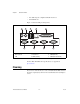
Chapter 1 General Information • Two USB 2.0 ports compliant with USB 1.0 and 1.1. • One PCI/104 slot Figure 1-1 shows the I/O port arrangement. 1 2 3 9 1 2 3 PS/2 Mouse PS/2 Keyboard USB 5 4 8 4 5 6 7 LAN Parallel Port COM1 (RS232) 6 7 8 9 COM2 (RS232) COM3 (RS232) COM4 (RS232/422/485) Figure 1-1. I/O Port Arrangement For more TPC-2012/TPC-2512 specifications, see Appendix A, Specifications. Cleaning If you need to clean the unit, use a soft, nonmetallic brush.
2 System Setup This chapter includes setup information for the TPC-2012/TPC-2512. Important Safety Information Before setting up the TPC-2012/TPC-2512, read these safety instructions carefully. Disconnect this equipment from any AC outlet before cleaning. Use a damp cloth. Do not use liquid or spray detergents for cleaning. For plug-in equipment, the power outlet socket must be located near the equipment and must be easily accessible. Keep this equipment away from excessive humidity.
Chapter 2 System Setup If one of the following situations arises, have service personnel check the equipment: • The power cord or plug is damaged. • Liquid has penetrated into the equipment. • The equipment has been exposed to moisture. • The equipment does not work well, or you cannot get it to work according to the user manual. • The equipment has been dropped and damaged. • The equipment has obvious signs of breakage.
Chapter 2 Caution System Setup Be sure system power is off before plugging in or pulling out the CompactFlash card. 2. Install a CompactFlash card containing Windows CE, embedded Windows XP, or another operating system. 3. Connect the power connector to 24 VDC power lines. Be sure to connect the positive, negative, and ground lines as shown in Figure 2-1. The power lines can be from either a power adapter or in-house power source. + – GND Figure 2-1. Power Connector 4.
Chapter 2 System Setup Panel Mounting Follow these steps to mount the TPC-2012/TPC-2512 in a panel: Note 1. Be sure the adhesive waterproof gasket on the front bezel is in position. 2. Install the TPC-2012/TPC-2512 in the panel opening. (Refer to Appendix A, Specifications, for cutout dimensions.) 3. Hook the clamps included in the accessory pack to the holes around the four sides of the bezel. 4. Insert the screws included in the accessory pack into the clamps.
3 Jumpers and Connectors This chapter describes the TPC-2012/TPC-2512 jumpers and connectors. Jumper and Connector Functions Table 3-1 lists the jumper and connector functions. Table 3-1.
Chapter 3 Jumpers and Connectors Table 3-1. Mainboard Connectors and Jumpers (Continued) Label TPC-2012/TPC-2512 User Manual Function Description JP1 Panel Panel connector JP2 Touch Touch connector JP4 5 V/3 V PCI104 5 V/3 V select J1 DDR DDR connector J3 1*3 pin header Clear CMOS SW1 Power switch System power switch BH1 Battery RTC battery FS1 Fuse Fuse holder 3-2 ni.
Chapter 3 Jumpers and Connectors Jumper and Connector Locations Figures 3-1 and 3-2 show the jumper and connector locations. Figure 3-1.
Chapter 3 Jumpers and Connectors Figure 3-2. Main Board Jumpers and Connectors TPC-2012/TPC-2512 User Manual 3-4 ni.
A Specifications This appendix lists the TPC-2012/TPC-2512 system specifications. Physical Weight .................................................... 4.1 kg (without HDD) Cutout dimensions..................................
Appendix A Specifications Dimensions 11 [0.433] 7 [0.079] 311 [12.244] 301.49 [11.869] 237 [9.331] 2.5 [0.098] 50 [1.969] 227.49 [8.956] TPC-2012/TPC-2512 User Manual A-2 ni.
Appendix A Specifications System Kernel CPU........................................................ GeodeLink Control Processor LX800 500 MHz BIOS....................................................... Award 512 KB flash memory South bridge ........................................... GeodeLink Control Processor CS5535 VGA ....................................................... GeodeLink Control Processor LX800 500 MHz Ethernet .................................................. Realtek RTL8100BL; IEEE 802.
Appendix A Specifications Backlight.................................................2 CCFL Backlight lifespan ...................................50,000 h There may be several bright or dark pixels on the LCD. This phenomenon is normal in LCD manufacturing. Note Touchscreen Touch type ..............................................Resistive Base glass construction...........................Tempered Glass Resolution ...............................................1024 × 1024 Light transmission .............
Appendix A Specifications Vibration ................................................ 1 grms (5 to 500 Hz) Maximum altitude .................................. 2,000 m Pollution Degree ....................................
Appendix A Specifications Environmental Management National Instruments is committed to designing and manufacturing products in an environmentally responsible manner. NI recognizes that eliminating certain hazardous substances from our products is beneficial not only to the environment but also to NI customers. For additional environmental information, refer to the NI and the Environment Web page at ni.com/environment.
B Serial Port Settings This appendix describes the TPC-2012/TPC-2512 serial port settings. COM1/COM2/COM3 Connector Pinout The following figure and table show the COM1/COM2/COM3 connector pinout. Note 1 5 6 9 Pin Signal 1 NDCD 2 NRX 3 NTX 4 NDTR 5 GND 6 NDSR 7 NRTS 8 NCTS 9 NRI COM1 and COM2 support only half-duplex (maximum baud rate: 115.2 Kbps).
Appendix B Serial Port Settings COM4 Connector Pinout and Settings The TPC-2012/TPC-2512 COM4 serial port is adjustable. You can set it to RS-232, RS-422, or RS-485, and it has auto data flow control capability. In other words, the TPC-2012/TPC-2512 can automatically detect the data flow direction at this port when two-wired RS-485 communication is activated. The following figure and table show the COM4 pinout and settings.
Appendix B © National Instruments Corporation Serial Port Settings PIN RS-232 RS-422 RS-485 1 NDCD TX– D– 2 NRX TX+ D+ 3 NTX RX+ 4 NDTR RX– 5 GND GND 6 NDSR 7 NRTS 8 NCTS 9 NRI B-3 GND TPC-2012/TPC-2512 User Manual
Watchdog Timer Programming C This appendix explains the TPC-2012/TPC-2512 watchdog timer programming. Overview You can use the TPC-2012/TPC-2512 watchdog timer to monitor system software operation and take corrective action if the software fails to function after the programmed period. This appendix describes how to program the watchdog timer operation. The watchdog timer is built into the W83627HF I/O controller.
Appendix C Watchdog Timer Programming Figure C-1 describes the watchdog timer programming procedure, and Table C-1 describes the watchdog timer registers. Unlock W83627 Select Watchdog Timer Register Enable Watchdog Timer Function Use Watchdog Timer Function Lock W83627HF Figure C-1. Watchdog Timer Programming Procedure TPC-2012/TPC-2512 User Manual C-2 ni.
Appendix C Watchdog Timer Programming Table C-1. Watchdog Timer Registers Address of Register (2E) Attribute Description Read/Write Value (2F) and description — 87 (hex) — Write this address twice to I/O address port 2E (hex) to unlock the W83627HF. 07 (hex) Write Write 08 (hex) to select the watchdog timer register. 30 (hex) Write Write 01 (hex) to enable the watchdog timer function. The default is disabled. F5 (hex) Write Set seconds or minutes as the timer unit.
Appendix C Watchdog Timer Programming Example Programs Example 1: Enable the Watchdog Timer and Set 10 s as the Timeout Interval ;----------------------------------------------------------Mov dx,2eh ; Unlock W83627HF Mov al,87h Out dx,al Out dx,al ;----------------------------------------------------------Mov al,07h ; Select registers of watchdog timer Out dx,al Inc dx Mov al,08h Out dx,al ;----------------------------------------------------------Dec dx ; Enable the function of watchdog timer Mov al,30h
Appendix C Watchdog Timer Programming Example 2: Enable the Watchdog Timer and Set 5 Min as the Timeout Interval ;----------------------------------------------------------Mov dx,2eh ; unlock W83627H Mov al,87h Out dx,al Out dx,al ;----------------------------------------------------------Mov al,07h ; Select registers of watchdog timer Out dx,al Inc dx Mov al,08h Out dx,al ;----------------------------------------------------------Dec dx ; Enable the function of watchdog timer Mov al,30h Out dx,al Inc dx
Appendix C Watchdog Timer Programming Example 3: Enable the Mouse to Reset the Watchdog Timer ;----------------------------------------------------------Mov dx,2eh ; unlock W83627H Mov al,87h Out dx,al Out dx,al ;----------------------------------------------------------Mov al,07h ; Select registers of watchdog timer Out dx,al Inc dx Mov al,08h Out dx,al ;----------------------------------------------------------Dec dx ; Enable the function of watchdog timer Mov al,30h Out dx,al Inc dx Mov al,01h Out dx,a
Appendix C Watchdog Timer Programming Example 4: Enable the Keyboard to Reset the Watchdog Timer ;----------------------------------------------------------Mov dx,2eh ; unlock W83627H Mov al,87h Out dx,al Out dx,al ;----------------------------------------------------------Mov al,07h ; Select registers of watchdog timer Out dx,al Inc dx Mov al,08h Out dx,al ;----------------------------------------------------------Dec dx ; Enable the function of watchdog timer Mov al,30h Out dx,al Inc dx Mov al,01h Out d
Appendix C Watchdog Timer Programming Example 5: Generate a Timeout Signal without Timer Counting ;----------------------------------------------------------Mov dx,2eh ; unlock W83627H Mov al,87h Out dx,al Out dx,al ;----------------------------------------------------------Mov al,07h ; Select registers of watchdog timer Out dx,al Inc dx Mov al,08h Out dx,al ;----------------------------------------------------------Dec dx ; Enable the function of watchdog timer Mov al,30h Out dx,al Inc dx Mov al,01h Out
Watchdog Timer Programming on WinCE (TPC-2012) D Windows CE includes a watchdog timer for the TPC-2012/TPC-2512. You can access the timer through the WIN32 API. The TPC-2012/TPC-2512 includes a WDT driver, WDT1:, for enabling/disabling the watchdog timer. You must open this driver before using the resources, and then use the DeviceIOControl function to enable/disable the watchdog timer. This appendix describes DeviceIOControl and it parameters. It also includes a programming example.
Appendix D Watchdog Timer Programming on WinCE (TPC-2012) • dwIoControlCode (in) Specifies the operation control code. This value identifies the specific operation to be performed and the type of device on which the operation is to be performed. No specific values are defined for the dwIoControlCode parameter. However, if you write a custom device driver, you can define IOCTL_XXXX control codes, per the CTL_CODE macro.
Appendix D Watchdog Timer Programming on WinCE (TPC-2012) How to Use the Control Codes There are six control codes for the WDT driver operation codes. IOCTL _WDT_ENABLE Enables the application watchdog timer. By default, if the watchdog timer is enabled, the WDT driver automatically triggers itself after the specified period, and your application does not need to trigger the watchdog timer.
Appendix D Watchdog Timer Programming on WinCE (TPC-2012) • lpOutBuffer: The DWORD points to your watchdog time setting. The watchdog time settings are: • Setting Time 0 2s 1 (default) 5 s (default) 2 10 s 3 15 s 4 30 s 5 45 s 6 60 s nOutBufferSize: unused IOCTL_WDT_SETTIMEOUT Sets the watchdog time setting. • TPC-2012/TPC-2512 User Manual lpInBuffer: The DWORD points to your watchdog time setting.
Appendix D Watchdog Timer Programming on WinCE (TPC-2012) IOCTL_WDT_REBOOT If you want your application to trigger the watchdog, use IOCTL_WDT_REBOOT to notify the watchdog driver timer (WDT). Otherwise, the WDT triggers itself automatically.
Appendix D Watchdog Timer Programming on WinCE (TPC-2012) While (1) { // do your job here. Sleep(8000); DeviceIoControl(m_hWDT, IOCTL_WDT_STROBE, NULL,0, NULL, 0, &dwTemp, NULL); } DeviceIoControl(m_hWDT, IOCTL_WDT_DISABLE, NULL, , NULL, 0, &dwTemp, NULL); CloseHandle(m_hWDT); TPC-2012/TPC-2512 User Manual D-6 ni.
E Features in Windows XP Embedded (TPC-2512) The TPC-2512 supports the Windows XP Embedded platform (commonly abbreviated XPe), which is a componentized version of the Windows XP Professional edition. This appendix explains the version information and the EWF utility for Windows XP Embedded. Version Information You can access the version information by selecting Start»All Programs» Utilities.
F Accessory Kit Assembly Procedure This appendix explains how to connect to a CD-ROM via the CompactFlash slot. CompactFlash to IDE Transfer Kit Assembly Follow these steps to connect to a CD-ROM via the CompactFlash slot: 1. Connect the IDE cable to the adapter board. 2. Insert the adapter board into the CompactFlash slot. 3. Connect the CD-ROM to the IDE cable. 4. Connect the external power line to the CD-ROM.
Touchscreen Configuration G This appendix explains how to configure the TPC-2012/TPC-2512 touchscreen using the PenMount Control Panel. Touchscreen Calibration (TPC-2012) To calibrate the TPC-2012, go to Start»Control Panel»Stylus, which displays the Stylus Properties screen. You can set the double-tap sensitivity in the Double-Tap tab. To recalibrate the stylus, use the Calibration tab.
H Fuse Replacement Caution Do not replace the fuse unless it is damaged. Do not replace the fuse with a differently rated fuse. For more information, see the fuse specifications in Appendix A, Specifications. Follow these steps to replace the fuse: 1. Remove the fuse cover. 2. Replace the damaged fuse with a new one. 3. Place the fuse cover back into position.
Technical Support and Professional Services I Visit the following sections of the award-winning National Instruments Web site at ni.com for technical support and professional services: • Support—Technical support resources at ni.com/support include the following: – Self-Help Technical Resources—For answers and solutions, visit ni.
Appendix I Technical Support and Professional Services If you searched ni.com and could not find the answers you need, contact your local office or NI corporate headquarters. Phone numbers for our worldwide offices are listed at the front of this manual. You also can visit the Worldwide Offices section of ni.com/niglobal to access the branch office Web sites, which provide up-to-date contact information, support phone numbers, email addresses, and current events. TPC-2012/TPC-2512 User Manual I-2 ni.
Index A E accessory kit assembly, F-1 electromagnetic compatibility specifications, A-5 Enhanced Write Filter (EWF), E-1 environmental management, A-6 environmental specifications, A-4 EWF, E-1 example programs watchdog timer, C-4 examples (NI resources), I-1 C CE compliance specifications, A-5 cleaning, 1-2, A-6 COM1/COM2/COM3 connector pinout, B-1 COM4 connector pinout and settings, B-2 CompactFlash to IDE transfer kit assembly, F-1 connectors, 3-1 function descriptions (table), 3-1 locations (table),
Index J software (NI resources), I-1 specifications, A-1 CE compliance, A-5 cleaning, 1-2, A-6 dimensions, A-2 electromagnetic compatibility, A-5 environmental, A-4 environmental management, A-6 fuse, A-4 LCD, A-3 mercury disposal and recycling, A-6 physical, A-1 power, A-4 safety, A-5 system kernel, A-3 touchscreen, A-4 Waste Electrical and Electronic Equipment compliance, A-6 Support, I-1 support, technical, I-1 system kernel specifications, A-3 system setup, 2-2 jumpers, 3-1 function descriptions (tab
Index TPC-2512 version information, E-1 Windows XP Embedded features, E-1 training and certification (NI resources), I-1 troubleshooting (NI resources), I-1 electromagnetic compatibility specifications, A-5 environmental management specifications, A-6 environmental specifications, A-4 fuse replacement, H-1 specifications, A-4 I/O ports, 1-1 introduction, 1-1 jumpers, 3-1 LCD specifications, A-3 mercury disposal and recycling specifications, A-6 panel mounting, 2-4 physical specifications, A-1 power connec