USER GUIDE SSR SERIES MODULES AND BACKPLANES This guide describes the mechanical and electrical aspects of the solid state relay (SSR) Series modules and backplanes. It also describes how to install and configure them for use with National Instruments data acquisition (DAQ) devices.
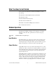
What You Need to Get Started To set up and use the SSR Series modules and backplanes you need the following: ❑ SSR Series module backplane kit and documentation ❑ SSR Series module ❑ National Instruments DAQ device ❑ Cable and/or SC-205X device ❑ Number 1 and number 2 Phillips-head screwdrivers ❑ ¼ in. flat-head screwdriver Module Operation SSR modules optically isolate the field signals from the computer, preventing any possibility of damage to the computer by overvoltage transients on these lines.
The dropout voltage and current specifications for the output modules are given in the Manufacturer Data Sheets section. For most control applications, such as controlling motors or lamps, these requirements are not difficult to meet. A second difference between these output modules and conventional relays is that they do not turn off completely. A small leakage current flows all the time even in the off state. For most control applications, this current causes no problems.
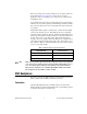
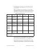
The SSR backplanes are divided into ports of eight modules each. The 8-, 16-, 24-, and 32-module backplanes have one, two, three, and four ports respectively. Table 2 shows backplanes that need an interface to convert the digital input/output (DIO) lines to map correctly. Table 2 also shows cables that are available for connecting DAQ devices and SSR backplanes. Refer to the National Instruments catalogue if your system is not listed in the table. Table 2.
! Caution Do not attempt to connect the SSR backplane to a host computer DAQ device for which it was not designed. Such connections can damage any or all SSR modules, the host computer, and the DAQ device. National Instruments is not liable for any damages resulting from incorrect connections. The 32-module backplane connects the PCLK1 (OUT1) and PCLK2 (OUT2) signals of the DIO-32HS (6533) device to ground.
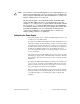
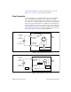
1 - 25/49 16 15 14 13 12 11 10 9 8 7 6 5 4 3 2 1 + AC INPUT AC OUTPUT DC INPUT DC OUTPUT + Y B W R 2 1 0 2 3 4 5 6 7 Note: No External Power Jumper Locations, remove all DAQ device power jumpers for external power connection. 1 DAQ Device Power Jumper Location (use only one) 2 Not Used Figure 1.
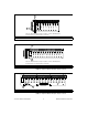
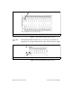
1 Note: No DAQ Device Power Jumper Location 1 External Power Fuse Figure 4. Grayhill 32 Module Backplane Jumper Locations Note The Grayhill 32-module backplane can be powered only by an external power supply. There are no jumper settings. There is a fuse on the external power supply. 1 2 3 1 External Power Jumper 2 DAQ Device Power Jumper 3 Not Used Figure 5.
1 2 3 1 External Power Jumper 2 DAQ Device Power Jumper 3 Not Used Figure 6. Crouzet 16 Module Backplane Jumper Locations 1 1 2 External Power Jumper 2 DAQ Device Power Jumper Figure 7. Crouzet 24 Module Backplane Jumper Locations Note The Crouzet 32 module backplane has no position on the backplane for either a fuse or jumper. You must add a power supply fuse elsewhere before connecting the power. Use a fuse that is suitable for your application.
output modules the LED is on when the module is turned on. See the Manufacturer Data Sheets section for further information. Signal Connections Connect external devices to the SSR modules using the screw terminals. Two screw terminals are dedicated to each module. Screw terminal pair 1 and 2 are for module 0, terminal pair 3 and 4 are for module 1, and so on.
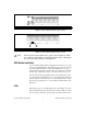
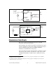
1.8 k User Signal Source 3 to 32 VDC Odd Backplane Terminal + – Digital Conversion Signal to DAQ Device Input DC Module Even Backplane Terminal 5A Figure 10. IDC5 Signal Connections Odd Backplane Terminal + 80 VDC – Even Backplane Terminal Voltage Spike Protection Digital Signal Conversion from DAQ Device Output Output DC Module Load Figure 11.
AC OUTPUT MODULES * FEATURES • Transient Protection: Meets the requirements of IEEE 472, “Surge Withstanding Capability Test” • SPST, Normally Open • Zero Crossing Turn-On • UL Recognized, CSA Certified • G5 Modules Passed IEC801.2, IEC801.3, and IEC801.
AC OUTPUT MODULES SPECIFICATIONS–All Modules Specifications apply over operating temperature range unless noted otherwise. Output Specifications Load Current Range (rms): 0.03 to 3.5 Amps for part numbers beginning 70 and 70G. 0.03 to 3.0 Amps for part numbers beginning 70M. Maximum current is limited by data noted in Figure 1. Maximum Surge Current (peak): 80 Amps at 60 Hz, 1 cycle; 25 Amps at 60Hz, 60 cycles as qualified by Figure 2.
DC OUTPUT MODULE * FEATURES • Transient Protection: Meets the requirements of IEEE 472, "Surge Withstanding Capability Test" • SPST, Normally Open • UL Recognized, CSA Certified • G5 Modules Passed IEC801.2, IEC801.3, and IEC801.4 • 4000 Vac Optical Isolation • G5 Modules Provide Replaceable 5 x 20 mm Glass Fuse and Built-in Status LED • Lifetime Warranty * •• TUV R h e i n l a n d 70G-ODC 70-ODC SEE CIRCUITRY AND DIMENSIONAL DRAWING FOR TERMINAL ID OF 70-ODC5R AND 70G-ODC5R.
DC OUTPUT MODULES SPECIFICATIONS Specifications apply over operating temperature range unless noted otherwise. Output Specifications Load Current Range: 0.02 to 3.5 Amps for part numbers beginning 70 and 70G; 0.02 to 3.0 Amps for 70M modules; 0.02 to 1.0 Amp for 70-ODC5A, 70M-ODC5A and 70G-ODC5A. Maximum current is limited by data noted in Figure 1. Power Dissipation:1.0 Watt/Amp typical; 1.5 Watt/Amp typ. for 70-ODC5A, 70M-ODC5A and 70G-ODC5A.
AC INPUT MODULE * FEATURES • Transient Protection: Meets the requirements of IEEE 472, “Surge Withstanding Capability Test” • G5 Modules Passed IEC801.2, IEC801.3, and IEC801.4 • UL Recognized, CSA Certified • 4000 Vac Optical Isolation • G5 Module has Built-in Status LED • Lifetime Warranty * •• TUV R h e i n l a n d 70G-IAC 70-IAC 70M-IAC CIRCUITRY Typical Logic Supply Current Versus Logic Supply Voltage For Figures 1 and 2, all values were measured at 25˚C.
AC INPUT MODULE SPECIFICATIONS–All Modules Specifications apply over operating temperature range unless noted otherwise. Output Specifications General Characteristics Materials and Finishes Output Current Range: 1-50 mA Breakdown Voltage: 50 Vdc minimum Off-State Leakage Current: 1 µA maximum Turn-on Time: 20 mSec maximum Turn-off Time: 20 mSec maximum On State Voltage Drop: 0.
DC INPUT MODULE * FEATURES • Transient Protection: Meets the requirements of IEEE 472, “Surge Withstanding Capability Test”** • Fast Switching Polarized Input Types • Non-Polarized Types Provide Inputs For AC or DC • UL Recognized, CSA Certified • G5 Modules Passed IEC801.2, IEC801.3, and IEC801.
DC INPUT MODULE SPECIFICATIONS–All Modules Specifications apply over operating temperature range unless noted otherwise. Output Specifications General Characteristics Materials and Finishes Output Current Range: 1-50 mA Breakdown Voltage: 50 Vdc minimum Off State Leakage Current: 1 µA maximum On State Voltage Drop: 0.
© National Instruments Corporation 19 SSR Series Modules and Backplanes
SSR Series Modules and Backplanes 20 © National Instruments Corporation
© National Instruments Corporation 21 SSR Series Modules and Backplanes
SSR Series Modules and Backplanes 22 © National Instruments Corporation
MOUNTING RACKS 8 MODULE RACK–Standard Part No. 70RCK8 Schematic and Ordering Information on page 54. Dimensions are shown in inches (and millimeters). All tolerances are ± 0.010 (0,25) unless otherwise specified. 8.00 (203,2) TERMINAL STRIP FOR LOGIC SUPPLY 16 15 14 13 12 11 10 9 8 7 6 5 4 3 2 1 + KEY SLOT PINS 5/7 3.00 (76,2) + 1 AC INPUT AC OUTPUT DC INPUT DC OUTPUT 1 + 0.30 (7,6) PIN 1 0 1 2 USER INSTALLABLE JUMPERS FOR +VCC (3 PLACES) 0.40 (10,2) 3.50 (88,9) Y B W R 1.
MOUNTING RACKS SCHEMATIC–Part Nos.
MOUNTING RACKS 16 MODULE RACK–Standard Part No. 70RCK16 Schematic and Ordering Information on pages 58-59. Dimensions are shown in inches (and millimeters). All tolerances are ± 0.010 (0,25) unless otherwise specified. 14.05 (356,9) 0.25 (6,4) 13.55 (344,2) 50 PIN EDGE CARD OR HEADER CONNECTOR FOR LOGIC SIGNALS (SEE NOTES) 0.40 (10,2) 5A FUSE FIELD WIRING TERMINAL STRIP LOGIC SUPPLY TERMINAL STRIP 0.
MOUNTING RACKS SCHEMATIC–Part Nos.
MOUNTING RACKS 24 MODULE RACK–Standard Part No. 70RCK24 Dimensions are shown in inches (and millimeters). Tolerances are ± 0.010 (0,25) unless indicated otherwise. 18.75 (476,3) 16.50 (419,1) 11.00 (279,4) STANDOFF I.D. 0.15 (3,8) DIA. (8 PLACES) CLEARANCE FOR #6 SCREWS 5.50 (139,7) 1.
MOUNTING RACKS 24 MODULE RACK–Miniature Part No. 70MRCK24 Dimensions are shown in inches (and millimeters). All tolerances are ± 0.010 (0,25) unless otherwise specified. 13.45 (341,6) 12.00 (304,8) FIELD WIRING TERMINAL STRIPS (3 PLACES) 8.00 (203,2) 5A FUSE 0.35 (8,9) 33 34 35 36 37 38 39 40 41 42 43 44 45 46 47 48 1 2 3 4 5 6 7 8 9 10 11 12 13 14 15 16 17 18 19 20 21 22 23 24 25 26 27 28 29 30 31 32 4.00 (101,6) 0.73 (18,5) 3.75 (95,3) 3.
© National Instruments Corporation 29 SSR Series Modules and Backplanes
SSR Series Modules and Backplanes 30 © National Instruments Corporation
© National Instruments Corporation 31 SSR Series Modules and Backplanes
SSR Series Modules and Backplanes 32 © National Instruments Corporation
© National Instruments Corporation 33 SSR Series Modules and Backplanes
SSR Series Modules and Backplanes 34 © National Instruments Corporation