SCXI ™ SCXI-1190/1191/1192 User Manual SCXI-1190/1191/1192 User Manual February 2001 Edition Part Number 322610B-01
Worldwide Technical Support and Product Information ni.
Important Information Warranty The SCXI-1190, SCXI-1191, and SCXI-1192 are warranted against defects in materials and workmanship for a period of one year from the date of shipment, as evidenced by receipts or other documentation. National Instruments will, at its option, repair or replace equipment that proves to be defective during the warranty period. This warranty includes parts and labor.
Compliance FCC/Canada Radio Frequency Interference Compliance* Determining FCC Class The Federal Communications Commission (FCC) has rules to protect wireless communications from interference. The FCC places digital electronics into two classes. These classes are known as Class A (for use in industrial-commercial locations only) or Class B (for use in residential or commercial locations). Depending on where it is operated, this product could be subject to restrictions in the FCC rules.
Canadian Department of Communications This Class B digital apparatus meets all requirements of the Canadian Interference-Causing Equipment Regulations. Cet appareil numérique de la classe B respecte toutes les exigences du Règlement sur le matériel brouilleur du Canada. European Union - Compliance to EEC Directives Readers in the EU/EEC/EEA must refer to the Manufacturer's Declaration of Conformity (DoC) for information** pertaining to the CE Mark compliance scheme.
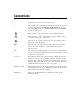
Conventions The following conventions are used in this manual: » The » symbol leads you through nested menu items and dialog box options to a final action. The sequence File»Page Setup»Options directs you to pull down the File menu, select the Page Setup item, and select Options from the last dialog box. This icon denotes a note, which alerts you to important information. This icon denotes a caution, which advises you of precautions to take to avoid injury, data loss, or a system crash.
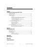
Contents Chapter 1 Installing and Configuring the SCXI-119X About the SCXI-119X....................................................................................................1-1 Installing the Software ...................................................................................................1-2 Safety Instructions .........................................................................................................1-3 Installing the Hardware..................................................
Contents Appendix C Technical Support Resources Glossary Index SCXI-1190/1191/1192 User Manual viii ni.
1 Installing and Configuring the SCXI-119X This manual describes the electrical and mechanical characteristics of the SCXI-1190 (quad 1 × 4, 50 Ω, 1.3 GHz bandwidth) and SCXI-1191 (quad 1 × 4, 50 Ω, 4 GHz bandwidth) multiplexer modules, and the SCXI-1192 (8-channel, SPDT, 50 Ω, 18 GHz bandwidth) relay module for the SCXI bus. It also contains information concerning their installation, operation, and safety instructions.
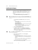
Chapter 1 Installing and Configuring the SCXI-119X Installing the Software You can control the SCXI-119X programmatically in an application development environment (ADE) using NI-SWITCH. The supported ADEs include LabVIEW, LabWindows/CVI, Visual Basic, and C or C++ environments. To install software for the SCXI-119X, complete the following: 1. Insert your NI-SWITCH software CD into your CD-ROM drive. The installation window should appear automatically.
Chapter 1 Installing and Configuring the SCXI-119X If a newer version of a driver is present on your PC, the installer will not overwrite the driver. Note Safety Instructions Cautions Do not operate damaged equipment. The safety protection features built into this instrument can become impaired if the instrument becomes damaged in any way. If the instrument is damaged, do not use it until service-trained personnel can check its safety.
Chapter 1 Installing and Configuring the SCXI-119X Unpacking Your SCXI-119X module is shipped in an antistatic package to prevent electrostatic damage to the module. Electrostatic discharge can damage several components on the module. To avoid such damage in handling the module, take the following precautions: Caution • Ground yourself using a grounding strap or by holding a grounded object.
Chapter 1 Installing and Configuring the SCXI-119X Follow these steps to install your SCXI-119X module into an SCXI chassis while referring to Figure 1-1 and your chassis documentation: 5 6 ® 7 MA SC IN FR XI AM E 8 1 2 4 3 1 2 3 4 Slot Slot Slot Slot 1 2 3 4 5 6 7 8 SCXI Chassis (SCXI-1000 Shown) SCXI Chassis Power Switch SCXI-119X (SCXI-1190 Shown) SCXI Module Thumbscrews Figure 1-1. Installing the SCXI-119X into an SCXI Chassis 1.
Chapter 1 Installing and Configuring the SCXI-119X Note When installing the SCXI-119X module in an SCXI chassis, fill slot 1 first, then fill slot 2 with the next SCXI-119X. 5. Insert any other SCXI modules into the remaining slots in the same manner as described in step 4. 6. Secure all the SCXI-119X modules to the SCXI chassis by tightening both module thumbscrews.
Chapter 1 Installing and Configuring the SCXI-119X To connect the chassis to a DAQ device, complete the following steps while referring to Figure 1-2: 1 4 3 ® 2 1 2 SCXI Chassis Power Switch Cable Adapter 3 4 Cable DAQ Device or Computer-Based Instrument Figure 1-2. Connecting an SCXI Chassis to a DAQ Device or Computer-Based Instrument 1. Power off both the SCXI chassis and the computer that contains the DAQ device or computer-based instrument. 2.
Chapter 1 Installing and Configuring the SCXI-119X 5. Check the cable installation, making sure the connectors are securely fastened at both ends. 6. Power on the SCXI chassis. 7. Power on the computer. 8. If you have already installed the appropriate software, you are ready to configure the SCXI-119X. If you have not installed the appropriate software, refer to the Installing the Software section.
Chapter 1 Installing and Configuring the SCXI-119X Configuring and Self-Testing the SCXI-119X Run Measurement & Automation Explorer (MAX) to configure and test your SCXI-119X. If you need help during the configuration process, open the Measurement & Automation Help file by selecting Help»Help Topics. 1. Double-click the Measurement & Automation Explorer icon on your desktop. 2. To add a new chassis, right-click Devices and Interfaces and select Create New. 3.
Chapter 1 Installing and Configuring the SCXI-119X Your SCXI chassis and SCXI-119X modules are now configured in the software with your modules. To configure the properties for a particular module, perform the following steps: 1. Expand Devices and Interfaces. You can see the chassis selected in the list. 2. Expand Chassis. 3. Right-click the module you want to configure and select Properties. Tabs are displayed containing attributes for different properties of the module.
Chapter 1 Installing and Configuring the SCXI-119X Self-Test Verification To test the successful configuration of your system, complete the following steps: 1. Double-click the Measurement & Automation Explorer icon on your PC desktop. 2. Verify that the chassis power is on and that the chassis is correctly connected to a DAQ device or computer-based instrument. 3. Expand Devices and Interfaces. 4. From the list of devices and interfaces that appears, locate the chassis you want to test.
Chapter 1 Installing and Configuring the SCXI-119X e. • • • • SCXI-1190/1191/1192 User Manual Change the Connected to selection from None to Connected to: Device x. If you get the warning message Failed to find followed by the module codes and the message Unable to communicate with chassis, take the following troubleshooting actions: a. Make sure that the SCXI chassis is powered on. b. Make sure the cable between the SCXI chassis and DAQ device or computer-based instrument is properly connected.
Chapter 1 Installing and Configuring the SCXI-119X Removing the SCXI-119X This section describes how to remove the SCXI-119X from an SCXI chassis. Removing the SCXI-119X from an SCXI Chassis Make sure you read and understand all the safety information in this manual before you remove an SCXI module. Consult the documentation for your SCXI or PXI (if you are using a combination chassis) chassis and accessories for additional instructions and warnings.
Chapter 1 Installing and Configuring the SCXI-119X 1. Turn off the SCXI chassis power. 2. Remove all signals connected to the SCXI-119X. Caution Do not remove the SCXI-119X module from a chassis that is turned on because doing so could damage the module. 3. Rotate the thumbscrews securing the SCXI-119X to the chassis counter-clockwise until they are loose, but do not completely remove the thumbscrews. 4.
Using the SCXI-119X 2 This chapter contains a functional overview and connection possibilities of the SCXI-119X modules. Functional Overview The SCXI-1190 uses single-pole double-throw, high-bandwidth relays capable of switching signals from DC to 1.3 GHz. Functionally identical, the SCXI-1191 has a bandwidth of DC to 4 GHz.
Chapter 2 Using the SCXI-119X Figure 2-1 illustrates the key functional components of the SCXI-1190/1191 multiplexer modules. Rear Signal Connector SCXIbus Relay Controller and Drivers Relay Control Bus comA 3A 2A 1A 0A comB 3B 2B 1B 0B comC 3C 2C 1C 0C comD 3D 2D 1D 0D Figure 2-1. SCXI-1190/1191 Modules Block Diagram SCXI-1190/1191/1192 User Manual 2-2 ni.
Chapter 2 Using the SCXI-119X Figure 2-2 illustrates the key functional components of the SCXI-1192 relay module. Rear Signal Connector SCXIbus Relay Controller com0 NC0 NO0 com1 NC1 NO1 com2 NC2 NO2 com3 NC3 NO3 com4 NC4 NO4 com5 NC5 NO5 com6 NC6 NO6 com7 NC7 NO7 Figure 2-2.
Chapter 2 Using the SCXI-119X SCXI backplane. National Instruments is not liable for any damages or injuries resulting from exceeding maximum voltage ratings. Refer to Appendix A, Specifications, for specific information. Always disconnect all signals from the front connectors and power off the SCXI chassis before removing the SCXI-119X from the chassis.
Chapter 2 Using the SCXI-119X Connecting Signals The SCXI-1190 has push-on SMB connectors, and the SCXI-1191/1192 have screw-on SMA connectors as shown in Figure 2-3. NATIONAL INSTRUMENTS NATIONAL INSTRUMENTS NATIONAL INSTRUMENTS Figure 2-3.
Chapter 2 Using the SCXI-119X Multiplexing to RF Sources Figure 2-4 shows how to use the SCXI-1190/1191 to select one of four RF sources to be routed to a RF measurement device. NATIONAL INSTRUMENTS RF Source 1 RF Source 2 RF Measurement Device • Scope • Spectrum Analyzer • Power Meter RF Source 3 RF Source 4 Figure 2-4. Connecting the SCXI-1190/1191 SCXI-1190/1191/1192 User Manual 2-6 ni.
Chapter 2 Using the SCXI-119X Figure 2-5 shows how to use the SCXI-1192 to route signals from two RF sources to one RF measurement device. NATIONAL INSTRUMENTS RF Source 1 RF Source 2 RF Measurement Device • Scope • Spectrum Analyzer • Power Meter Figure 2-5.
Chapter 2 Using the SCXI-119X Expanding the RF Multiplexer Figure 2-6 shows how to expand the SCXI-1190/1191 by cascading stages together. In the specific case of Figure 2-6, the module is used to create a 13-to-1 multiplexer with a two-stage architecture. You can cascade several modules to provide even larger multiplexers. Cascading multiplexers increases insertion loss, creates propagation delays, and can have other RF effects.
Chapter 2 Using the SCXI-119X Figure 2-7 shows one possible expansion using two SCXI-1192 modules. In this case, the switches on two SCXI-1192 modules are interconnected to create a 2 × 4 matrix. Multiple configurations are possible using one or more SCXI-1192 modules. Cascading switches increases insertion loss, creates propagations delays, and can have other RF effects.
A Specifications This appendix lists the specifications for the SCXI-1190, the SCXI-1191, and the SCXI-1192 multiplexer modules. These specifications are typical at 25 °C unless otherwise noted. SCXI-1190 Input Characteristics Number of banks.................................... 4 Number of channels per bank ................ 4 Common-mode voltage Channel to earth .............................. 24 Vrms or DC Maximum switching voltage AC ................................................... 24 Vrms DC .......
Appendix A Specifications for SCXI-1190 RF Performance Characteristics Characteristic impedance (Z0) ................50 Ω Insertion loss at: ≤100 MHz........................................<0.4 dB ≤500 MHz........................................<0.9 dB ≤1.3 GHz .........................................<1.5 dB ≤2 GHz ............................................<3 dB VSWR at: ≤100 MHz........................................<1.15 ≤500 MHz........................................<1.35 ≤1.3 GHz ................
Appendix A Specifications for SCXI-1190 Expected life Mechanical (no load) ...................... 5 × 10⁶ operations Electrical at maximum switching capacity........................... 105 operations Exceeding the maximum switching capability decreases the expected life of the SCXI-1190. Caution Power Requirement +5 VDC Maximum (all relays closed) .......... 600 mA Physical Dimensions............................................. 17.30 by 19.56 by 3.02 cm (6.81 by 7.70 by 1.19 in.) I/O connectors ......
Appendix A Specifications for SCXI-1190 product, and a link to the DoC (in Adobe Acrobat format) appears. Click the Acrobat icon to download or read the DoC. Safety Designed in accordance with IEC 61010-1, UL 3111-1, and CAN/CSA C22.2 No. 1010.1 for electrical measuring and test equipment. Installation category II1 Pollution degree 2 Certifications and Compliances CE Mark Compliance See the Declaration of Conformity sheet accompanying product.
Appendix A Specifications for SCXI-1191 SCXI-1191 Input Characteristics Number of banks.................................... 4 Number of channels per bank ................ 4 Common-mode voltage Channel to earth .............................. 30 Vrms or DC Maximum switching voltage AC ................................................... 30 Vrms DC ................................................... 30 VDC Maximum switching capacity per channel AC ................................................... 0.
Appendix A Specifications for SCXI-1191 Isolation: < 2.5 GHz ........................................< –60 dB < 4 GHz ...........................................< –55 dB Maximum RF carry power at 900 MHz .............................................10 W Refer to the warning and cautions in Chapter 2, Using the SCXI-119X, for important information about using your SCXI-1191 with high-power signals. Note Dynamic Characteristics Relay operate time (at 20 °C) Typical.........................................
Appendix A Specifications for SCXI-1191 Environment Operating temperature ..........................0 to 50 °C Storage temperature..............................–20 to 70 °C Relative humidity ................................... 10% to 90% noncondensing Electromagnetic Compatibility EMC/EMI............................................... CE, C-Tick, and FCC Part 15 (Class A) Compliant Electrical emissions................................ EN 55011 Class A at 10 m FCC Part 15A above 1 GHz Electrical immunity..
Appendix A Specifications for SCXI-1192 SCXI-1192 Input Characteristics Number of relays ....................................8 Number of channels per relay.................2 Common-mode voltage Channel to earth...............................30 Vrms or DC Maximum switching voltage DC....................................................30 VDC Maximum carry current per channel DC....................................................2 A Maximum continuous input power per channel (continuous wave) 1–3 GHz........
Appendix A Specifications for SCXI-1192 8 to 12.4 GHz.................................. ≤1.35 12.4 to 18 GHz................................ ≤1.5 Isolation: ≤1 GHz............................................ ≤–85 dB 1 to 4 GHz....................................... ≤–80 dB 4 to 8 GHz....................................... ≤–70 dB 8 to 12.4 GHz.................................. ≤–65 dB 12.4 to 18 GHz................................
Appendix A Specifications for SCXI-1192 Environment Operating temperature ......................... 0 to 50 °C Storage temperature ............................. –20 to 70 °C Relative humidity ...................................10% to 90% noncondensing Electromagnetic Compatibility EMC/EMI ...............................................CE, C-Tick, and FCC Part 15 (Class A) Compliant Electrical emissions ................................EN 55011 Class A at 10 m FCC Part 15A above 1 GHz Electrical immunity .
B Common Questions This appendix addresses common questions you may have while using your SCXI-119X switching module. The SCXI-1190 is listed to have a 1.3 GHz bandwidth. Can I use it at 2 GHz bandwidth? The SCXI-1190 can definitely be used at 2 GHz, as long as the isolation, VSWR, and attenuation levels are acceptable for your particular application. Refer to Appendix A, Specifications, for a complete list of the parameters at 2 GHz.
Appendix B Common Questions What is VSWR, and how does it affect my system? VSWR stands for Voltage Standing Wave Ratio; it is a measure of the reflection on a transmission line. The percentage of a signal reflected back to the source is equal to (VSWR-1)/(VSWR+1). This means that a VSWR of 1 is optimum, with no reflected signal. On higher power applications, a large VSWR can damage the output stage of the source.
Technical Support Resources C Web Support National Instruments Web support is your first stop for help in solving installation, configuration, and application problems and questions. Online problem-solving and diagnostic resources include frequently asked questions, knowledge bases, product-specific troubleshooting wizards, manuals, drivers, software updates, and more. Web support is available through the Technical Support section of ni.com NI Developer Zone The NI Developer Zone at ni.
Appendix C Technical Support Resources Worldwide Support National Instruments has offices located around the world to help address your support needs. You can access our branch office Web sites from the Worldwide Offices section of ni.com. Branch office Web sites provide up-to-date contact information, support phone numbers, e-mail addresses, and current events.
Glossary Prefix Meanings Value n- nano- 10 –9 m- milli- 10 –3 M- mega- 10 6 G- giga- 10 9 Symbols ° degrees Ω ohms % percent A A amperes AC alternating current ADC amperes, direct current ADE application development environment such as LabVIEW, LabWindows/CVI, Visual Basic, and C or C++ Arms amperes, root-mean-square C C Celsius channel pin or wire lead on the switch to which you apply or from which you read the analog or digital signal.
Glossary D DAQ data acquisition dB decibel DC direct current device a plug-in board, card, or pad that can contain multiple channels and conversion devices. Some examples of devices are computers, multimeters, multiplexers, oscillators, operator interfaces, and counters.
Glossary N NI-SWITCH an IVI-based instrument driver that supports the National Instruments line of switch cards P PXI PCI with eXtensions for Instrumentation R RF radio frequency relay a switch that connects or disconnects the signal to a common through the physical movement of a metal arm rms root mean square—the square root of the average value of the square of the instantaneous signal amplitude; a measure of signal amplitude S s seconds SCXI Signal Conditioning eXtensions for Instrumentatio
Glossary Vrms volts, root-mean-square VSWR Voltage Standing Wave Ratio W W watts SCXI-1190/1191/1192 User Manual G-4 ni.
Index A D auto-detection of modules, 1-9 to 1-10 DAQ device. See connecting SCXI-119X to DAQ device.
Index power requirement specifications SCXI-1190, A-3 SCXI-1191, A-6 SCXI-1192, A-9 PXI combination chassis, connecting with SCXI-119X, 1-8 installation, 1-2 to 1-8 connecting SCXI-119X to DAQ device DAQ device or computer-based instrument, 1-6 to 1-8 in PXI combination chassis, 1-8 removing SCXI-119X, 1-13 to 1-14 from Measurement & Automation Explorer, 1-14 from SCXI chassis, 1-13 to 1-14 into SCXI chassis, 1-4 to 1-6 software installation, 1-2 to 1-3 unpacking, 1-4 isolation, defined, B-2 Q questions
Index electromagnetic compatibility, A-7 environment, A-7 input characteristics, A-5 physical, A-6 power requirement, A-6 RF performance characteristics, A-5 to A-6 safety, A-7 SCXI-1192, A-8 to A-10 dynamic characteristics, A-9 electromagnetic compatibility, A-10 environment, A-10 input characteristics, A-8 physical, A-9 power requirements, A-9 RF performance characteristics, A-8 to A-9 safety, A-10 system integration, by National Instruments, C-1 SCXI-119X block diagrams, 2-2 to 2-3 common questions, B-