SCXI ™ SCXI-1190/1191 User Manual SCXI-1190/1191 User Manual February 2000 Edition Part Number 322610A-01
Worldwide Technical Support and Product Information www.ni.
Important Information Warranty The SCXI-1190 and SCXI-1191 are warranted against defects in materials and workmanship for a period of one year from the date of shipment, as evidenced by receipts or other documentation. National Instruments will, at its option, repair or replace equipment that proves to be defective during the warranty period. This warranty includes parts and labor.
Compliance FCC/Canada Radio Frequency Interference Compliance* Determining FCC Class The Federal Communications Commission (FCC) has rules to protect wireless communications from interference. The FCC places digital electronics into two classes. These classes are known as Class A (for use in industrialcommercial locations only) or Class B (for use in residential or commercial locations). Depending on where it is operated, this product could be subject to restrictions in the FCC rules.
• • Connect the equipment into an outlet on a circuit different from that to which the receiver is connected. Consult the dealer or an experienced radio/TV technician for help. Canadian Department of Communications This Class B digital apparatus meets all requirements of the Canadian Interference-Causing Equipment Regulations. Cet appareil numérique de la classe B respecte toutes les exigences du Règlement sur le matériel brouilleur du Canada.
Conventions The following conventions are used in this manual: This icon denotes a note, which alerts you to important information. This icon denotes a caution, which advises you of precautions to take to avoid injury, data loss, or a system crash. This icon denotes a warning, which advises you of precautions to take to avoid being electrically shocked. bold Bold text denotes items that you must select or click on in the software, such as menu items and dialog box options.
Contents Chapter 1 Installing and Configuring the SCXI-119X About the SCXI-119X....................................................................................................1-1 Installing the Software ...................................................................................................1-1 Installing the Hardware..................................................................................................1-2 Unpacking....................................................................
Contents Appendix C Technical Support Resources Glossary Index Figures Figure 1-1. Figure 1-2. Figure 1-3. Installing the SCXI-119X into an SCXI Chassis .................................. 1-3 Connecting an SCXI Chassis to a DAQ Device or Computer-Based Instrument ................................................................. 1-6 Removing the SCXI-119X .................................................................... 1-13 Figure 2-1. Figure 2-2. Figure 2-3. Figure 2-4.
Installing and Configuring the SCXI-119X 1 This manual describes the electrical and mechanical characteristics of the SCXI-1190 (quad 1 × 4, 50 Ω, 1.3 GHz bandwidth) and the SCXI-1191 (quad 1 × 4, 50 Ω, 4 GHz bandwidth) multiplexer modules for the SCXI bus and contains information concerning their installation and operation. About the SCXI-119X This section summarizes the features and operation of the SCXI-119X switch modules.
Chapter 1 Installing and Configuring the SCXI-119X 2. Install the NI-SWITCH software that came on a CD with your SCXI-119X. The CD includes the software required to configure and to program your SCXI-119X module. a. Insert your National Instruments NI-SWITCH software CD into the CD-ROM drive. b. Click Install in the installation window that will appear automatically. Note If the installation window does not appear, double-click the My Computer icon on your PC desktop.
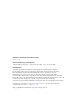
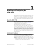
Chapter 1 Installing and Configuring the SCXI-119X Installing the SCXI-119X Module into an SCXI Chassis You need the following items to complete the installation: • SCXI-119X module • SCXI chassis Follow these steps to install your SCXI-119X module into an SCXI chassis while referring to Figure 1-1. 5 6 ® 7 SC MA IN XI FR AM E 8 1 2 3 1 2 3 Slot 1 Slot 2 Slot 3 4 5 6 4 Slot 4 SCXI Chassis SCXI Chassis Power Switch 7 8 SCXI-119X (SCXI-1191 Shown) SCXI Module Thumbscrews Figure 1-1.
Chapter 1 Installing and Configuring the SCXI-119X 4. Insert the SCXI-119X module into slot 1. Gently guide the module into the module guides and push it to the back of the slot until the connectors make good contact. The module must be firmly engaged; however, do not force the module into place. If the module is not sliding easily into the chassis, check for correct insertion into the module guides.
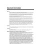
Chapter 1 Installing and Configuring the SCXI-119X To connect the chassis to a DAQ device for multiplexed operation, complete the following steps while referring to Figure 1-2: 1. Turn off both the SCXI chassis and the computer that contains the DAQ device or computer-based instrument. 2. Insert the cable adapter into the back of the SCXI chassis aligned with the module that is to be connected to the DAQ device or computer-based instrument.
Chapter 1 Installing and Configuring the SCXI-119X 1 4 3 ® 2 1 2 SCXI Chassis Power Switch Cable Adapter 3 4 Cable DAQ Device or Computer-Based Instrument Figure 1-2.
Chapter 1 Installing and Configuring the SCXI-119X You should have already installed your SCXI-119X module and any other SCXI modules in the chassis according to their installation instructions. To use the SCXI-119X module with a DAQ device or computer-based instrument in a PXI combination chassis, turn on the SCXI chassis. Consult your PXI chassis documentation, other SCXI module documentation, and DAQ device or computer-based instrument documentation for additional instructions and warnings.
Chapter 1 Installing and Configuring the SCXI-119X You now have the choice of automatically detecting which modules are installed in the chassis or manually adding them. • If you have just added the chassis to Devices and Interfaces, you can automatically detect new modules. • If the chassis was already listed in Devices and Interfaces, you must manually add new modules. Go to the appropriate section that follows to continue the software configuration of your chassis.
Chapter 1 Installing and Configuring the SCXI-119X Note If the Measurement & Automation Explorer recognized any module as an SCXI custom module, you may be using an old version of NI-DAQ, the data acquisition driver software. You can download the latest version of NI-DAQ for free at www.ni.com. Manually Adding Modules If you did not auto-detect your SCXI modules, you must add each of your modules separately. Use the following steps to manually add modules: 1.
Chapter 1 Installing and Configuring the SCXI-119X Your SCXI chassis and SCXI module(s) should now be configured properly. If your configuration is complete, test the system as described in the Self-Test Verification section to ensure that your SCXI system is communicating properly with the device. Self-Test Verification To test the successful configuration of your system, complete the following steps: 1. Double-click the Measurement & Automation Explorer icon on your PC desktop: 2.
Chapter 1 2. Installing and Configuring the SCXI-119X c. Click the + next to your SCXI chassis to show all the SCXI modules. d. Right-click on the module that is connected to your DAQ device or computer-based instrument and select Properties. e. Change the Connected to selection from None to Connected to: Device x. If you get the warning message Failed to find followed by the module codes and the message Unable to communicate with chassis, take the following troubleshooting actions: a.
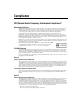
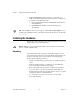
Chapter 1 Installing and Configuring the SCXI-119X Removing the SCXI-119X This section describes how to remove the SCXI-119X from an SCXI chassis. Removing the SCXI-119X from an SCXI Chassis Make sure you read and understand all the safety information in this manual before you remove an SCXI module. You need the following items to complete this task: • SCXI chassis with the SCXI-119X module(s) installed • 1/4 in.
Chapter 1 Installing and Configuring the SCXI-119X 2 1 ® SC MA IN XI FR AM E 3 4 1 2 SCXI Chassis Power Switch SCXI Chassis 3 4 SCXI-119X (SCXI-1191 Shown) SCXI Module Thumbscrews Figure 1-3. Removing the SCXI-119X Removing the SCXI-119X from Measurement & Automation Explorer To remove a module from Measurement & Automation Explorer, complete the following steps: 1. Double-click the Measurement & Automation Explorer icon on your PC desktop. 2.
Chapter 1 Installing and Configuring the SCXI-119X Note Deleting an SCXI chassis deletes all modules in the chassis. All configuration information for these modules is also lost. Your SCXI chassis and/or SCXI module(s) should now be removed from the list of installed devices in Measurement & Automation Explorer. SCXI-1190/1191 User Manual 1-14 www.ni.
Using the SCXI-119X 2 This chapter contains a functional overview, safety instructions, and connection possibilities of the SCXI-119X multiplexer module. Functional Overview The SCXI-119X modules are general-purpose, quad 4-channel, high-bandwidth multiplexing switches. The SCXI-1190 uses single-pole double-throw, high-bandwidth relays capable of switching signals from DC to 1.3 GHz. Functionally identical, the SCXI-1191 has a bandwidth of DC to 4 GHz.
Chapter 2 Using the SCXI-119X SCXI-1190 SCXI-1191 Hardware Architecture Rear Signal Connector SCXIbus Relay Controller and Drivers Relay Control Bus comA 3A 2A 1A 0A comB 3B 2B 1B 0B comC 3C 2C 1C 0C comD 3D 2D 1D 0D Figure 2-1. SCXI-119X Module Block Diagram Safety Instructions Cautions Do not operate damaged equipment. The safety protection features built into this instrument can become impaired if the instrument becomes damaged in any way.
Chapter 2 Using the SCXI-119X Connections that exceed any of the maximum signal ratings on the SCXI-119X can create a shock or fire hazard or can damage any or all of the devices connected to the SCXI-119X. National Instruments is not liable for any damages or injuries resulting from incorrect signal connections. Clean the instrument and accessories by brushing off light dust with a soft, nonmetallic brush. Remove other contaminants with a stiff nonmetallic brush.
Chapter 2 Using the SCXI-119X Connecting Signals The SCXI-1190 has push-on SMB connectors, and the SCXI-1191 has screw-on SMA connectors as shown in Figure 2-2. N ATION AL IN STRUMEN TS N ATION AL IN STRUMEN TS Figure 2-2. SCXI-1190 SMB Connectors, SCXI-1191 SMA Connectors Note The power-up and reset state of the different multiplexer banks are as follows: banks A and C, channel 0 is connected to the COM terminal; banks B and D, channel 3 is connected is connected to the COM terminal.
Chapter 2 Using the SCXI-119X Multiplexing to RF Sources Figure 2-3 shows how to use the SCXI-119X to select one of four RF sources to be routed to a RF measurement device. N ATION AL IN STRUMEN TS RF Source 1 RF Source 2 RF Measurement Device • Scopes • Spectrum Analyzers • Power Meters RF Source 3 RF Source 4 Figure 2-3.
Chapter 2 Using the SCXI-119X Expanding the RF Multiplexer Figure 2-4 shows how to expand the SCXI-119X by cascading stages together. In the specific case of Figure 2-4, the module is used to create a 13 to 1 multiplexer with a two-stage architecture. You can cascade several modules to provide even larger multiplexers. Cascading multiplexers increases insertion loss, creates propagation delays, and may have other RF effects.
A Specifications This appendix lists the specifications for the SCXI-1190 and the SCXI-1191 multiplexer modules. These specifications are typical at 25 °C unless otherwise noted. SCXI-1190 Input Characteristics Number of relays per bank..................... 3 Number of banks.................................... 4 Common-mode voltage Channel to earth .............................. 24 VDC Maximum switching voltage AC ................................................... 24 Vrms DC ............................
Appendix A Specifications for SCXI-1190 RF Performance Characteristics Characteristic impedance (Z0) ................50 Ω Insertion loss at: ≤100 MHz........................................<0.4 dB ≤500 MHz........................................<0.9 dB ≤1.3 GHz .........................................<1.5 dB ≤2 GHz ............................................<3 dB VSWR at: ≤100 MHz........................................<1.15 ≤500 MHz........................................<1.35 ≤1.3 GHz ................
Appendix A Specifications for SCXI-1190 Exceeding the maximum switching capability will decrease the expected life of the SCXI-1190. Caution Power Requirement +5 VDC Maximum (all relays closed) .......... 600 mA Physical Dimensions............................................. 17.30 by 19.56 by 3.02 cm (6.81 by 7.70 by 1.19 in.) I/O connector.......................................... 5 SMB female per bank Environment Operating temperature ..........................0 to 50 °C Storage temperature........
Appendix A Specifications for SCXI-1191 SCXI-1191 Input Characteristics Number of relays per bank .....................3 Number of banks ....................................4 Common-mode voltage Channel to earth...............................30 Vrms or DC Maximum switching voltage AC....................................................30 Vrms DC....................................................30 VDC Maximum switching capacity per channel DC....................................................30 VDC at 0.
Appendix A Specifications for SCXI-1191 Note Refer to the warning and cautions in Chapter 2, Using the SCXI-119X, for important information about using your SCXI-1191 with high-power signals. Dynamic Characteristics Relay operate time (at 20 °C) Typical ............................................ 15 ms Relay release time (at 20 °C) Typical ............................................ 15 ms Expected life Mechanical (no load) ......................
Appendix A Specifications for SCXI-1191 Certifications and Compliances CE Mark Compliance See the Declaration of Conformity sheet accompanying product. SCXI-1190/1191 User Manual A-6 www.ni.
B Common Questions This appendix addresses common questions you may have while using your SCXI-119X multiplexer module. The SCXI-1190 is listed to have a 1.3 GHz bandwidth. Can I use it at 2 GHz bandwidth? The SCXI-1190 can definitely be used at 2 GHz, as long as the isolation, VSWR, and attenuation levels are acceptable for your particular application. Refer to Appendix A, Specifications, for a complete list of the parameters at 2 GHz.
Appendix B Common Questions One of my modules doesn’t switch properly anymore. What’s wrong? One of the relays has probably worn out. Relays are mechanical devices and have a limited switching lifetime. Call National Instruments for information on replacing your relays. What is VSWR, and how does it affect my system? VSWR stands for Voltage Standing Wave Ratio; it is a measure of the reflection on a transmission line. The percentage of a signal reflected back to the source is equal to (VSWR-1)/(VSWR+1).
Technical Support Resources C This appendix describes the comprehensive resources available to you in the Technical Support section of the National Instruments Web site and provides technical support telephone numbers for you to use if you have trouble connecting to our Web site or if you do not have internet access. NI Web Support To provide you with immediate answers and solutions 24 hours a day, 365 days a year, National Instruments maintains extensive online technical support resources.
Appendix C Technical Support Resources Software-Related Resources • Instrument Driver Network—A library with hundreds of instrument drivers for control of standalone instruments via GPIB, VXI, or serial interfaces. You also can submit a request for a particular instrument driver if it does not already appear in the library. • Example Programs Database—A database with numerous, non-shipping example programs for National Instruments programming environments.
Glossary Prefix Meanings Value n- nano- 10 –9 m- milli- 10 –3 M- mega- 10 6 G- giga- 10 9 Symbols ° degrees Ω ohms % percent A A amperes AC alternating current ADE application development environment such as LabVIEW, LabWindows/CVI, Visual Basic, and C or C++ C C Celsius channel pin or wire lead on the multiplexer to which you apply or from which you read the analog or digital signal. Signals can be single-ended or differential.
Glossary dB decibel DC direct current device a plug-in board, card, or pad that can contain multiple channels and conversion devices. Some examples of devices are computers, multimeters, multiplexers, oscillators, operator interfaces, and counters.
Glossary N NI-SWITCH an IVI-based instrument driver that supports the National Instruments line of switch cards O oz ounce P PXI PCI with extensions for instrumentation R RF radio frequency relay a switch that connects or disconnects the signal to a common through the physical movement of a metal arm rms root mean square—the square root of the average value of the square of the instantaneous signal amplitude; a measure of signal amplitude S s seconds SCXI Signal Conditioning eXtensions for I
Glossary V V volts VDC volts, direct current VSWR Voltage Standing Wave Ratio W W SCXI-1190/1191 User Manual watts G-4 www.ni.
Index A E auto-detection of modules, 1-8 to 1-9 environment specifications SCXI-1190, A-3 SCXI-1191, A-5 expanding RF multiplexer, 2-6 B block diagram of SCXI-119X, 2-2 H C hardware installation. See installation.
Index SCXI-1191, A-4 to A-6 RF sources, multiplexing to, 2-5 RF switching precautions, 2-3 troubleshooting, 1-10 to 1-11 multiplexed operation with DAQ device, 1-5 multiplexer, expanding, 2-6 multiplexing to RF sources, 2-5 S N safety instructions, 2-2 to 2-3 SCXI chassis installing SCXI-119X into, 1-3 to 1-4 removing SCXI-119X from, 1-12 to 1-13 SCXI-119X block diagram, 2-2 common questions, B-1 to B-2 configuration and self-test, 1-7 to 1-11 connecting signals, 2-4 to 2-6 contact protection, 2-3 func
Index V SCXI-1191, A-4 to A-5 certifications and compliances, A-5 dynamic characteristics, A-5 environment, A-5 input characteristics, A-4 physical, A-5 power requirement, A-5 RF performance characteristics, A-4 to A-6 Voltage Standing Wave Ratio (VSWR), B-2 W Web support from National Instruments, C-1 to C-2 online problem-solving and diagnostic resources, C-1 software-related resources, C-2 Worldwide technical support, C-2 T technical support resources, C-1 to C-2 troubleshooting common problems, B-1