
Network Card User Manual

SCXI-1163 Cabling Appendix E
SCXI-1163 User Manual E-4 © National Instruments Corporation
SCXI-1341 Lab-NB, Lab-PC, or Lab-PC+ and SCXI-1344
Lab-LC Cable Assembly
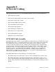
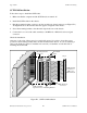
The SCXI-1341 Lab-NB, Lab-PC, or Lab-PC+ cable assembly connects a Lab-NB, Lab-PC, or
Lab-PC+ board to an SCXI-1163 module. The SCXI-1344 Lab-LC cable assembly connects a
Lab-LC board to an SCXI-1163 module. The SCXI-1341 and SCXI-1344 cable assemblies
consist of two pieces–an adapter board and a 50-conductor ribbon cable that connects the Lab
board to the rear connector of the adapter board. The adapter board converts the signals from the
Lab board I/O connector to a format compatible with the SCXI-1163 rear signal connector pinout
at the front connector of the SCXI-1341 or SCXI-1344. The adapter board also has an additional
male breakout connector that provides the unmodified Lab board signals for use with an
SCXI-1180 feedthrough panel or SCXI-1181 breadboard module. The adapter board gives the
Lab boards full access to the digital control lines. The position of jumper W1 on the SCXI-1341
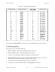
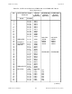
and SCXI-1344 is irrelevant because the SCXI-1163 does not use jumper W1. Table E-2 lists the
SCXI-1341 and SCXI-1344 pin translations.
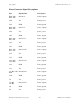
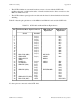
Table E-2. SCXI-1341 and SCXI-1344 Pin Translations
Lab Board Pin Lab Board Signal SCXI-1163 Pin SCXI-1163 Signal
1 ACH0 3 No Connect
2 ACH1 5 No Connect
3 ACH2 7 No Connect
4 ACH3 9 No Connect
5 ACH4 11 No Connect
6 ACH5 13 No Connect
7 ACH6 15 No Connect
8 ACH7 17 No Connect
9 AIGND 1-2 No Connect
10 DAC0OUT 20 No Connect
11 AOGND 23 No Connect
12 DAC1OUT 21 No Connect
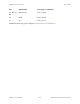
13, 50 DGND 24 DIG GND
26 PB4 25 SERDATIN
27 PB5 27 DAQD*/A
28 PB6 29 SLOT0SEL*
29 PB7 37 SERCLK
31 PC1 26 SERDATOUT
32 PC2 28 No Connect
40 EXTCONV* 36 No Connect
43 OUTB1 46 No Connect
49 +5 V 34-35 No Connect
All other pins of the Lab board pinout are not sent to the SCXI-1163 rear signal connector.