SCXI™-1161 User Manual 8-Channel Power Relay Module SCXI-1161 User Manual March 1999 Edition Part Number 320514C-01 © Copyright 1993, 1999 National Instruments Corporation. All Rights Reserved.
Worldwide Technical Support and Product Information www.natinst.
Important Information Warranty The SCXI-1161 is warranted against defects in materials and workmanship for a period of one year from the date of shipment, as evidenced by receipts or other documentation. National Instruments will, at its option, repair or replace equipment that proves to be defective during the warranty period. This warranty includes parts and labor.
Table of Contents About This Manual Organization of This Manual ........................................................................................ ix Conventions Used in This Manual................................................................................ x National Instruments Documentation ........................................................................... xi Related Documentation.................................................................................................
Table of Contents Chapter 3 Signal Connections Screw Terminal Connections ....................................................................................... 3-1 Contact Protection for Inductive Load Connections .................................................... 3-1 Signal Connection .......................................................................................... 3-4 Rear Signal Connector..................................................................................................
Table of Contents Figure 3-3. SCXI-1161 Rear Signal Connector Pin Assignment ............................. 3-5 Figure 4-1. Figure 4-2. Figure 4-3. SCXI-1161 Block Diagram ................................................................... 4-2 Digital Interface Circuitry Block Diagram ............................................ 4-3 SCXI-1161 Digital Control.................................................................... 4-4 Tables Table 2-1. Table 2-2. Configuration of Jumpers W1 and W2 ..........
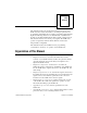
About This Manual This manual describes the electrical and mechanical aspects of the SCXI-1161 and contains information concerning its operation and programming. The SCXI-1161 is a member of the National Instruments Signal Conditioning eXtensions for Instrumentation (SCXI) Series modules for the National Instruments data acquisition plug-in boards. This module switches and controls power signals. The SCXI-1161 operates as eight relay channels. Each channel is isolated and independently configurable.
About This Manual • Appendix C, Customer Communication, contains forms you can use to request help from National Instruments or to comment on our products. • The Glossary contains an alphabetical list and description of terms used in this manual, including abbreviations, acronyms, metric prefixes, mnemonics, and symbols. • The Index contains an alphabetical list of key terms and topics in this manual, including the page where you can find each one.
About This Manual monospace Lowercase text in this font denotes text or characters that are to be literally input from the keyboard, sections of code, programming examples, and syntax examples. This font is also used for the proper names of disk drives, paths, directories, programs, subprograms, subroutines, device names, functions, variables, filenames, and extensions, and for statements and comments taken from program code. NB NB refers to the NuBus series computers.
About This Manual documentation sets and the NI-DAQ documentation. After you set up your hardware system, use either the application software (LabVIEW or LabWindows/CVI) or the NI-DAQ documentation to help you write your application. If you have a large, complicated system, it is worthwhile to look through the software documentation before you configure your hardware.
Chapter 1 Introduction This chapter describes the SCXI-1161; lists the contents of your SCXI-1161 kit; describes the optional software, optional equipment, and custom cables; and explains how to unpack the SCXI-1161 kit. About the SCXI-1161 The SCXI-1161 consists of eight isolated single-pole double-throw (SPDT), or one form C, relay channel. With the SCXI-1161, the SCXI chassis can serve as a controller or switcher in laboratory testing, production testing, and industrial-process monitoring.
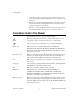
Chapter 1 Introduction Software Programming Choices There are several options to choose from when programming your National Instruments DAQ or SCXI hardware. You can use LabVIEW, LabWindows/CVI, ComponentWorks, VirtualBench, NI-DAQ, or register-level programming. National Instruments Application Software LabVIEW features interactive graphics, a state-of-the-art user interface, and a powerful graphical programming language.
Chapter 1 Introduction NI-DAQ Driver Software The NI-DAQ driver software is included at no charge with all National Instruments DAQ hardware. NI-DAQ is not packaged with SCXI or accessory products, except for the SCXI-1200. NI-DAQ has an extensive library of functions that you can call from your application programming environment.
Chapter 1 Introduction Conventional Programming Environment ComponentWorks, LabVIEW, LabWindows/CVI, or VirtualBench NI-DAQ Driver Software DAQ or SCXI Hardware Personal Computer or Workstation Figure 1-1. The Relationship between the Programming Environment, NI-DAQ, and Your Hardware Register-Level Programming The final option for programming any National Instruments DAQ hardware is to write register-level software.
Chapter 1 Introduction Optional Equipment National Instruments offers a variety of products to use with your SCXI-1611, including cables and other accessories as follows: • Cables and cable assemblies • Multichassis adapter • One-slot cable extender For more specific information about these products, refer to your National Instruments catalogue or call the office nearest you. Custom Cables The SCXI-1161 rear signal connector is a 50-pin male ribbon-cable header.
Chapter 1 Introduction Unpacking Your SCXI-1161 module is shipped in an antistatic package to prevent electrostatic damage to the module. Electrostatic discharge can damage several components on the module. To avoid such damage in handling the module, take the following precautions: SCXI-1161 User Manual • Ground yourself via a grounding strap or by holding a grounded object. • Touch the antistatic package to a metal part of your SCXI chassis before removing the module from the package.
Chapter Configuration and Installation 2 This chapter describes the SCXI-1161 jumper configurations, installation of the SCXI-1161 into the SCXI chassis, signal connections to the SCXI-1161, and cable wiring. Module Configuration The SCXI-1161 includes five jumpers, shown in Figure 2-1.
Chapter 2 Configuration and Installation SCXI-1161 User Manual Thumbscrew Arc Suppressor Pads Product Name Assembly Number W2 Rear Signal Connector W1 Strain Relief Bar 2-2 © National Instruments Corporation Figure 2-1.
Chapter 2 ! Caution: Configuration and Installation DO NOT OPERATE THE DEVICE IN AN EXPLOSIVE ATMOSPHERE OR WHERE THERE MAY BE FLAMMABLE GASES OR FUMES. KEEP AWAY FROM LIVE CIRCUITS. Do not remove equipment covers or shields unless you are trained to do so. If signal wires are connected to the device, hazardous voltages may exist even when the equipment is turned off.
Chapter 2 Configuration and Installation Connect the signal wires to the screw terminals by inserting the stripped end of the wire full into the terminals. Tighten the terminals to a torque of 5 to 7 in.-lb. Connections, including power signals to ground and vice versa, that exceed any of the maximum signal ratings on the SCXI device can create a shock or fire hazard or can damage any or all of the boards connected to the SCXI chassis, the host computer, and the SCXI device.
Chapter 2 Configuration and Installation Jumper Use Use the jumpers as follows: • Jumper W1 connects a pullup resistor to the SERDATOUT signal on the rear signal connector. • Jumper W2 carries the SCXIbus MISO line, after buffering, to the SERDATOUT signal on the rear signal connector. • Jumpers W3, W4, and W5 select whether the SCXI-1161 is to be connected to a DIO-type board or to an MIO-type board. DIO-type boards are National Instruments boards that have only digital inputs and outputs.
Chapter 2 Configuration and Installation Jumper W2 Position 1 connects the SCXIbus MISO line, after buffering, to the SERDATOUT pin of the rear signal connector. This is the factory-default setting. In this setting, along with the proper setting of jumper W1, the data acquisition board can read the Module ID Register of the SCXI-1161. See the SCXI Register-Level Programmers Manual, for information on reading the Module ID Register.
Chapter 2 Configuration and Installation Table 2-1.
Chapter 2 Configuration and Installation Table 2-2. Configuration of Jumpers W3, W4, and W5 for DIO-Type and MIO-Type Boards Jumper Configuration for DIO-Type Board (Factory Setting) Configuration for MIO-Type Board W3 MIO W3 DIO MIO W3 DIO W4 MIO W4 DIO MIO W4 DIO W5 MIO W5 DIO MIO W5 DIO Jumpers W3, W4, and W5 You can use two types of data acquisition boards with the SCXI-1161-DIO-type boards and MIO-type boards.
Chapter 2 Configuration and Installation Hardware Installation You can install the SCXI-1161 in any available SCXI chassis. After you have made any necessary changes and have verified and recorded the jumper settings on the form in Appendix C, Customer Communication, you are ready to install the SCXI-1161. The following are general installation instructions; consult the user manual or technical reference manual of your SCXI chassis for specific instructions and warnings. Note: 1.
Chapter 3 Signal Connections This section describes the signal connections to the SCXI-1161 board via the SCXI-1161 screw terminals and rear signal connector, and includes specifications and connection instructions for the SCXI-1161 connector signals. Screw Terminal Connections The SCXI-1161 has 24 screw terminals for easy signal connection to the inputs. Each input consists of a common (COM) position, a normally closed (NC) position, and a normally open (NO) position.
Chapter 3 Signal Connections + VDC Inductive Load V Flyback Diode COM NO NC Figure 3-1. Contact Protection Using a Flyback Diode for DC Inductive Loads In addition, the module has pads on which you can place an arc suppressor protection circuit to limit the voltage spike generated during the switching of inductive loads. These pads are between the COM position and the NO position and between the COM position and the NC position of the relays.
Chapter 3 Signal Connections Table 3-2. Arc Suppressor Placement, COM to NC COM to NC Channel Number Transient Voltage Suppressor Reference Designator 0 VR2 1 VR4 2 VR6 3 VR8 4 VR10 5 VR12 6 VR14 7 VR16 Figure 3-2 shows how to connect a transient voltage suppressor for AC and DC inductive loads. NC VR2 Relay COM VR1 Arc Suppressor Pads NO Figure 3-2.
Chapter 3 Signal Connections Signal Connection To connect the signal to the screw terminals, use the following procedure: 1. Remove the grounding screw of the top cover. 2. Snap out the top cover of the shield by placing a screwdriver in the groove at the bottom of the module. 3. Install contact protection, preferably across your load, as described in the previous section, if your load is inductive. 4. Slide the signal wires one at a time through the front panel strain relief.
Chapter 3 Signal Connections Figure 3-3 shows the pin assignments for the SCXI-1161 rear signal connector. SERDATIN DAQD*/A SLOT0SEL* (DIO) SERCLK (MIO) SERCLK (DIO) SERDATOUT 1 3 5 7 9 11 13 15 17 19 21 23 25 27 29 31 33 35 37 39 41 43 45 47 49 2 4 6 8 10 12 14 16 18 20 22 24 26 28 30 32 34 36 38 40 42 44 46 48 50 DIG GND (MIO) SERDATOUT (MIO) DIG GND (DIO) Figure 3-3.
Chapter 3 Signal Connections Rear Signal Connector Signal Descriptions Table 3-3 shows the rear signal connector signal descriptions. Table 3-3. Rear Signal Connector Signal Descriptions Pin SCXI-1161 User Manual Signal Name Description 24 or 50 DIG GND Digital Ground—Supplies the reference for data acquisition board digital signals and is tied to the module digital ground. Pin 50 is for DIO-type boards. Pin 24 is for MIO-type boards. Jumper W3 selects the pin.
Chapter 3 Signal Connections Table 3-3. Rear Signal Connector Signal Descriptions (Continued) Pin Signal Name Description 29 SLOT0SEL* Slot 0 Select—Taps into the SCXIbus INTR* line to indicate whether the information on MOSI is sent to a module or to Slot 0. 31 or 37 SERCLK Serial Clock—Taps into the SCXIbus SPICLK line to clock the data on the MOSI and MISO lines. Pin 31 is for DIO-type boards. Pin 37 is for MIO-type boards. Jumper W4 selects the pin. * Indicates active low.
Chapter 3 Signal Connections Table 3-4 lists the pin equivalences. For more information, consult the installation guide of your cable. Table 3-4.
Chapter 4 Theory of Operation This chapter contains a functional overview of the SCXI-1161 module and explains the operation of each functional unit making up the SCXI-1161. Functional Overview The block diagram in Figure 4-1 shows the key functional components of the SCXI-1161.
Chapter 4 Theory of Operation Arc Suppressor Pads Relays 0 through 7 NC(0) COM(0) Module ID Register NO(0) NC(1) COM(1) Data Register NO(1) Rear Signal Connector Digital Interface NC(6) COM(6) NO(6) SCXIbus Connector NC(7) COM(7) NO(7) Figure 4-1.
Chapter 4 Theory of Operation The major components of the SCXI-1161 are as follows: • The digital interface • The digital control circuitry • The relay channels The SCXI-1161 module is dedicated to switching and controlling power signal sources. The theory of operation of each of the SCXI-1161 components is explained in the rest of this chapter. Digital Interface Figure 4-2 shows a diagram of the SCXI-1161 and SCXIbus digital interface circuitry.
Chapter 4 Theory of Operation signals from the data acquisition board and the SCXIbus and sends signals back and forth between the data acquisition board and the SCXIbus. Digital Control Circuitry Figure 4-3 diagrams the SCXI-1161 digital control. Module ID Register Serial Data Out Buffered Serial Data In Data Register Buffered Digital Control Signals NO <7..4> NO <3..0> Figure 4-3. SCXI-1161 Digital Control The digital control section consists of the Data Register and the Module ID Register.
Chapter 4 Theory of Operation Relay Channels The SCXI-1161 has eight independent one form C (single-pole double-throw) relays. Each relay has three connections at the front screw terminals–the common (COM), the normally closed (NC), and the normally open (NO) positions. Each relay has pads for arc suppressors to protect the relays from inductive loads. Refer to the Contact Protection for Inductive Load Connections section of Chapter 3, Signal Connections, for further details on contact protection.
Appendix A Specifications This appendix lists the specifications for the SCXI-1161. These are typical at 25° C and 50% humidity unless otherwise stated. The operating temperature range is 0° to 50° C. Channel Rating Maximum switching capacity (resistive load)1 AC ...............................................8 A at 125 VAC 6 A at 250 VAC DC ...............................................5 A at 30 VDC Switching current................................
Appendix A Specifications Operate time....................................... 15 msec Release time ....................................... 15 msec Physical Dimensions ........................................ 1.2 by 6.8 by 8.0 in. Connectors ......................................... 50-pin male ribbon-cable rear connector 24-screw terminal adapter Operating Environment Temperature ...................................... 0 to 50 °C Relative humidity ...............................
Appendix B Contact Protection This appendix contains technical data on contact protection when you are switching inductive loads.1 1 Copyright © Aromat Corporation, 1991. Reprinted with permission of copyright owner. All rights reserved. Aromat Corporation. 1991 Relay Technical Data Book.
Appendix B Contact Protection SCXI-1161 User Manual B-2 © National Instruments Corporation
Appendix B © National Instruments Corporation B-3 Contact Protection SCXI-1161 User Manual
Appendix B Contact Protection SCXI-1161 User Manual B-4 © National Instruments Corporation
Appendix B © National Instruments Corporation B-5 Contact Protection SCXI-1161 User Manual
Appendix B Contact Protection SCXI-1161 User Manual B-6 © National Instruments Corporation
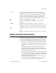
Appendix Customer Communication C This appendix describes the comprehensive resources available to you in the Technical Support section of the National Instruments Web site and provides technical support telephone numbers for you to use if you have trouble connecting to our Web site or if you do not have internet access. NI Web Support To provide you with immediate answers and solutions 24 hours a day, 365 days a year, National Instruments maintains extensive online technical support resources.
Software-Related Resources • Instrument Driver Network—A library with hundreds of instrument drivers for control of standalone instruments via GPIB, VXI, or serial interfaces. You also can submit a request for a particular instrument driver if it does not already appear in the library. • Example Programs Database—A database with numerous, nonshipping example programs for National Instruments programming environments.
Technical Support Form Photocopy this form and update it each time you make changes to your software or hardware, and use the completed copy of this form as a reference for your current configuration. Completing this form accurately before contacting National Instruments for technical support helps our applications engineers answer your questions more efficiently.
SCXI-1161 Hardware and Software Configuration Form Record the settings and revisions of your hardware and software on the line to the right of each item. Complete a new copy of this form each time you revise your software or hardware configuration, and use this form as a reference for your current configuration. Completing this form accurately before contacting National Instruments for technical support helps our applications engineers answer your questions more efficiently.
Documentation Comment Form National Instruments encourages you to comment on the documentation supplied with our products. This information helps us provide quality products to meet your needs. Title: SCXI™-1161 User Manual Edition Date: March 1999 Part Number: 320514C-01 Please comment on the completeness, clarity, and organization of the manual.
Glossary Prefix Meaning Value p- pico- 10–12 n- nano- 10–9 µ- micro- 10–6 m- milli- 10–3 k- kilo- 103 M- mega- 106 Numbers/Symbols ° degrees Ω ohms +5 V (signal) +5 VDC Source A A amperes AC alternating current A/D analog-to-digital AWG American Wire Gauge © National Instruments Corporation G-1 SCXI-1161 User Manual
Glossary C C Celsius CHS Chassis CHSGND Chassis Ground COM common cpm cycles per minute D D/A digital-to-analog D*/A Data/Address DAQD*/A Data Acquisition Board Data/Address Line DC direct current DIG GND Digital Ground DIO digital I/O F FIFO first-in-first-out ft feet H hex hexadecimal HSCR Hardscan Control Register Hz hertz SCXI-1161 User Manual G-2 © National Instruments Corporation
Glossary I I/O input/output II input current leakage Iin input current in.
Glossary R RAM random-access memory RESET* reset RMA Return Material Authorization rms root mean square RTSI Real-Time System Integration S SCXI Signal Conditioning eXtensions for Instrumentation (bus) SDK Software Developer’s Kit sec seconds SERCLK Serial Clock SERDATIN Serial Data In SERDATOUT Serial Data Out SL Slot SLOT0SEL* Slot 0 Select SPDT single-pole double-throw SPI Serial Peripheral Interface SPICLK Serial Peripheral Interface Clock SS* Slot Select U UL SCXI-11
Glossary V V volts V+ Positive Analog Supply V– Negative Analog Supply VAC volts alternating current VDC volts direct current VIH volts input high VIL volts input low Vin volts in VOH volts output high VOL volts output low Vout volts out Vrms volts, root mean square W W watts © National Instruments Corporation G-5 SCXI-1161 User Manual
Index A custom cables, 1-5 customer communication, xii, C-1 to C-2 arc suppressor pad locations (figure), 3-3 arc suppressor placement COM to NC (table), 3-3 COM to NO (table), 3-2 D D*/A signal, SCXIbus to SCXI-1161 pin equivalencies (table), 3-8 DAQD*/A signal description (table), 3-6 SCXIbus to SCXI-1161 pin equivalencies (table), 3-8 DIG GND signal (table), 3-6 digital control circuitry, 4-4 digital interface circuitry, 4-3 to 4-4 digital I/O signal connections, 3-7 documentation conventions used in
Index M flyback voltage. See contact protection for inductive load connections. FTP support, C-1 MIO boards, jumper W3, W4, and W5 configuration (table), 2-8 MISO signal jumper W1 and W2 connections, 2-5 to 2-7 SCXIbus to SCXI-1161 pin equivalencies (table), 3-8 module configuration. See configuration. MOSI signal, SCXIbus to SCXI-1161 pin equivalencies (table), 3-8 H hardware installation, 2-9 I inductive load connections, contact protection for. See contact protection for inductive load connections.
Index S arc suppressor placement COM to NC (table), 3-3 COM to NO (table), 3-2 flyback diode for DC inductive loads (figure), 3-2 signal connection procedure, 3-4 rear signal connector, 3-4 to 3-8 digital I/O connections, 3-7 pin assignments (figure), 3-5 SCXIbus to SCXI-1161 pin equivalencies (table), 3-8 signal descriptions (table), 3-6 to 3-7 screw terminal connections, 3-1 SLOT0SEL* signal description (table), 3-7 SCXIbus to SCXI-1161 pin equivalencies (table), 3-8 software programming choices, 1-2 to
Index functional overview, 4-1 to 4-3 relay channels, 4-5 SCXI-1161 block diagram, 4-2 V VirtualBench software, 1-2 SCXI-1161 User Manual I-4 © National Instruments Corporation