SCXI -1122 TM User Manual Sixteen-Channel Isolated Transducer Multiplexer Module for Signal Conditioning September 1999 Edition Part Number 320516B-01 © Copyright 1993, 1999 National Instruments Corporation. All Rights Reserved.
Worldwide Technical Support and Product Information www.natinst.
Warranty The SCXI-1122 is warranted against defects in materials and workmanship for a period of one year from the date of shipment, as evidenced by receipts or other documentation. National Instruments will, at its option, repair or replace equipment that proves to be defective during the warranty period. This warranty includes parts and labor.
WARNING REGARDING USE OF NATIONAL INSTRUMENTS PRODUCTS (1) NATIONAL INSTRUMENTS PRODUCTS ARE NOT DESIGNED WITH COMPONENTS AND TESTING FOR A LEVEL OF RELIABILITY SUITABLE FOR USE IN OR IN CONNECTION WITH SURGICAL IMPLANTS OR AS CRITICAL COMPONENTS IN ANY LIFE SUPPORT SYSTEMS WHOSE FAILURE TO PERFORM CAN REASONABLY BE EXPECTED TO CAUSE SIGNIFICANT INJURY TO A HUMAN.
Contents About This Manual .............................................................................................................ix Organization of This Manual .........................................................................................ix Conventions Used in This Manual .................................................................................x The National Instruments Documentation Set ...............................................................xi Related Documentation .......
Contents Chapter 5 Calibration .............................................................................................................................5-1 Overview ........................................................................................................................5-1 Calibration Procedure ....................................................................................................5-1 Calibration Equipment Requirements .........................................................
Contents Figures Figure 1-1. The Relationship between the Programming Environment, NI-DAQ, and Your Hardware...................................................................................................1-3 Figure 2-1. SCXI-1122 Parts Locator Diagram ....................................................................2-2 Figure Figure Figure Figure Figure 3-7. Figure 3-8. SCXI-1122 Front Connector Pin Assignments ..................................................
About This Manual This manual describes the electrical and mechanical aspects of the SCXI-1122 and contains information concerning its operation. The SCXI-1122 is a member of the National Instruments Signal Conditioning eXtensions for Instrumentation (SCXI) Series for the National Instruments DAQ plug-in boards.
About This Manual Conventions Used in This Manual The following conventions are used in this manual. ! This symbol refers to a caution that must be taken when operating this equipment. This symbol is found on the equipment and near the explanation of the caution in the manual. bold italic Bold italic text denotes a note, caution, or warning. italic Italic text denotes emphasis, a cross reference, or an introduction to a key concept.
About This Manual The National Instruments Documentation Set The SCXI-1122 User Manual is one piece of the documentation set for your SCXI system. You should have six types of manuals. Use these different types of manuals as follows: • Getting Started with SCXI–This is the first manual you should read. It gives an overview of the SCXI system and contains the most commonly needed information for the modules, chassis, and software.
About This Manual Customer Communication National Instruments wants to receive your comments on our products and manuals. We are interested in the applications you develop with our products, and we want to help if you have problems with them. To make it easy for you to contact us, this manual contains comment and configuration forms for you to complete. These forms are in Appendix B, Customer Communication, at the end of this manual.
Chapter 1 Introduction This chapter describes the SCXI-1122; lists the contents of your SCXI-1122 kit; describes the optional software, optional equipment, and custom cables; and explains how to unpack the SCXI-1122. The SCXI-1122 has 16 isolated input channels and two isolated excitation channels. The SCXI-1122 is a module for signal conditioning of strain gauges, RTDs, thermistors, thermocouples, volt and millivolt sources, 4 to 20 mA current sources, and 0 to 20 mA processcurrent sources.
Introduction Chapter 1 Software Programming Choices There are four options to choose from when programming your National Instruments plug-in DAQ board and SCXI hardware. You can use LabVIEW, LabWindows, NI-DAQ, or registerlevel programming software. LabVIEW and LabWindows Application Software LabVIEW and LabWindows are innovative program development software packages for data acquisition and control applications.
Chapter 1 Introduction NI-DAQ also internally addresses many of the complex issues between the computer and the plug-in board such as programming interrupts and DMA controllers. NI-DAQ maintains a consistent software interface among its different versions so that you can change platforms with minimal modifications to your code. Figure 1-1 illustrates the relationship between NI-DAQ and LabVIEW and LabWindows.
Introduction Chapter 1 Register-Level Programming The final option for programming any National Instruments DAQ hardware is to write registerlevel software. Writing register-level programming software can be very time consuming and inefficient, and is not recommended for most users. The only users who should consider writing register-level software should meet at least one of the following criteria: • National Instruments does not support your operating system or programming language.
Chapter 1 Introduction Custom Cables The SCXI-1122 rear signal connector is a 50-pin male ribbon-cable header. The manufacturer part number that National Instruments uses for this header is as follows: • AMP Inc. (part number 1-103310-0) The mating connector for the SCXI-1122 rear signal connector is a 50-position polarized ribbon-socket connector with strain relief. National Instruments uses a polarized or keyed connector to prevent inadvertent upside-down connection to the SCXI-1122.
Chapter 2 Configuration and Installation This chapter describes how to configure the SCXI-1122 jumpers and how to install the SCXI-1122 into the SCXI chassis. Module Configuration The SCXI-1122 contains two jumpers that are shown in the parts locator diagram in Figure 2-1. Jumper W2 connects a pullup resistor to the SERDATOUT signal on the rear signal connector. Jumper W1 configures the guard and the analog output ground, and enables the pseudodifferential reference mode.
Configuration and Installation Chapter 2 Figure 2-1.
Chapter 2 Configuration and Installation Digital Signal Connections Note: If nothing is cabled to the SCXI-1122 rear signal connector, the position of jumper W2 is irrelevant. The SCXI-1122 has one jumper–jumper W2–for communication between the DAQ board and the SCXIbus, shown in Table 2-1. Table 2-1. Digital Signal Connection Jumper Settings Position 3 (unmarked position, no pullup)–Use this setting for additional chassis in a multichassis system. No pullup resistor is connected to the SERDATOUT line.
Configuration and Installation Chapter 2 Table 2-2. Jumper W1 Settings Configuration Unconnected position (factory setting) B A R0 R1 R2 Connects the analog reference to the analog output ground AOGND (pins 1 and 2 on the rear signal connector). Select this configuration if you are using an RSE DAQ board. Do not use a differential input DAQ board when jumper W1 is in this position.
Chapter 2 Configuration and Installation Table 2-3. User-Defined Current Receiver Resistors (Continued) Input Channel Resistor Reference Designator 4 5 6 7 8 9 10 11 12 13 14 15 Warning: R5 R6 R7 R8 R9 R10 R11 R12 R13 R14 R17 R18 Before installing the resistors in your module, make sure that there are no signals connected to your module front connector. ! SHOCK HAZARD –This unit should only be opened by qualified personnel aware of the dangers involved.
Configuration and Installation Chapter 2 Hardware Installation You can install the SCXI-1122 in any available SCXI chassis slot. After you have made any necessary changes and have verified and recorded the jumper settings on the form in Appendix B, Customer Communication, you are ready to install the SCXI-1122. The following are general installation instructions; consult the user manual or technical reference manual of your SCXI chassis for specific instructions and warnings. 1.
Chapter 3 Signal Connections This chapter describes the input and output signal connections to the SCXI-1122 module via the SCXI-1122 front connector and rear signal connector. This chapter also includes specifications and connection instructions for the signals on the SCXI-1122 connectors. The following warnings contain important safety information concerning hazardous voltages.
Signal Connections Chapter 3 Connections, including power signals to ground and vice versa, that exceed any of the maximum signal ratings on the SCXI-1122 can damage any or all of the boards connected to the SCXI chassis, the host computer, and the SCXI-1122 module. National Instruments is NOT LIABLE FOR ANY DAMAGES OR INJURIES resulting from incorrect signal connections. If high voltages (≥ 30 Vrms, 42.
Chapter 3 Signal Connections Front Connector Figure 3-1 shows the pin assignments for the SCXI-1122 front connector. ! If a relay fails there exists a potential shock hazard on the inputs that are not in contact with hazardous voltages. For this reason treat all inputs as potentially hazardous if any inputs are in contact with hazardous voltages (≥ 30 Vrms, 42.4 Vpk or 60 Vdc).
Signal Connections Chapter 3 Front Signal Connection Descriptions Pin Signal Name Description A1 TEMP- Temperature Sensor Reference–This pin is tied to the temperature sensor reference in the terminal block and to the isolation amplifier negative input in the module. A3 TEMP+ Temperature Sensor Output–This pin connects the temperature sensor output to the amplifier input selector. A7 +5 V +5 VDC Isolated Source–This pin, which powers the temperature sensor on the terminal block, has 0.
Chapter 3 Signal Connections The signals on the front connector are all analog except pins A7, and A31, which are digital. The analog signals are grouped into analog input channels, excitation channels, and temperature sensor signals. Signal connection guidelines for each of these groups are described in the following sections. Notes: All pins are overvoltage protected to 250 Vrms except for pin A7 (+5 V signal), pin 31 (RSVD), pin A17 (SENSE+), and pin A11 (VEX/2).
Signal Connections Chapter 3 + - Vs Vcm Figure 3-2. Ground-Referenced Signal Connection with High Common-Mode Voltage + Vs Figure 3-3. Floating Signal Connection Referenced to Chassis Ground for Better SNR Cc Vs + - Rb Figure 3-4.
Chapter 3 Signal Connections Cc Vs + - Rb Vcm Figure 3-5. AC-Coupled Signal Connection with High Common-Mode Voltage For AC-coupled signals, connect an external resistor from the positive input channel to the signal reference to provide the DC path for the positive input bias current. Typical resistor values range from 100 kΩ to 1 MΩ.
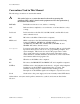
Signal Connections Scanned 100 times Chapter 3 CH0 (one sample) CH1 (one sample) CH2 (one sample) CH0 x 100 samples CH3 (one sample) CH1 x 100 samples No 100 Scans Done? CH2 x 100 samples CH3 x 100 samples Yes average the samples for each channel average the samples for each channel a. Bad technique—hardware-driven scanning wears out relays 100 times faster than the software-driven scanning. b. Good technique—softwaredriven scanning saves relay life. Figure 3-6.
Chapter 3 Signal Connections Table 3-1. Maximum Load per Excitation Channel Excitation Level Maximum Load 3.333 V 1 mA 225 mA 5 kΩ Using the Internal Half-Bridge Completion Your SCXI-1122 includes half-bridge completion for half-bridge and quarter-bridge setups. The completion network consists of two 2.5 kΩ ±0.02% ratio tolerance resistors with a temperature coefficient of 2 ppm/°C. These resistors are connected in series.
Signal Connections Chapter 3 Rear Signal Connector Note: If you are using the SCXI-1122 with a National Instruments DAQ board and cable assembly, you do not need to read the remainder of this chapter. If you are using the SCXI-1180 feedthrough panel, the SCXI-1343 rear screw terminal adapter, or the SCXI-1351 one-slot cable extender with the SCXI-1122, read this section. Figure 3-8 shows the SCXI-1122 rear signal connector pin assignments.
Chapter 3 Signal Connections Rear Signal Connection Descriptions Pin Signal Name Description 1, 2 AOGND Analog Output Ground–These pins are connected to the analog reference when jumper W1 is in position AB-R0. 3, 4 MCH0± Analog Output Channels 0–Connects to the DAQ board differential analog input channels. 19 OUTREF Output Reference–This pin serves as the reference node for the analog channels output in the pseudodifferential reference mode.
Signal Connections Chapter 3 In particular, when using differential input DAQ boards such as the MIO-16 boards, it is preferable to leave jumper W1 in its factory setting or in position AB-R1 to avoid ground loops. With DAQ boards that are configured for referenced single-ended (RSE) measurements, set jumper W1 in position AB-R0 to connect the SCXI-1122 ground to the DAQ analog ground. Pin 19 is the OUTREF pin; this pin is connected internally to the analog reference when jumper W1 is in position AB-R2.
Chapter 3 Signal Connections Table 3-2. SCXIbus to SCXI-1122 Rear Signal Connector to DAQ Board Pin Equivalences SCXIbus Line MOSI D*/A INTR* SPICLK MISO SCXI-1122 Rear Signal Connector SERDATIN DAQD*/A SLOT0SEL* SERCLK SERDATOUT MIO-16 Lab Boards PC-LPM-16 ADIO0 ADIO1 ADIO2 EXTSTROBE* BDIO0 PB4 PB5 PB6 PB7 PC1 DOUT4 DOUT5 DOUT6 DOUT7 DIN6 The digital timing signals are pins 36, 43, and 46.
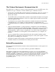
Chapter 4 Theory of Operation This chapter contains a functional overview of the SCXI-1122 module and explains the operation of each functional unit making up the SCXI-1122. Functional Overview The block diagram in Figure 4-1 illustrates the key functional components of the SCXI-1122.
SCXI-1122 User Manual 4-2 SENSE+ VEX+ VEX/2 VEXSENSE- IEX+ IEX- TEMP+ TEMPRSVD CH15 CH8 CH7 CH0 - + - + - + - + 8 Input Relays Protection 8 InputT/Output Relays Temp Voltage Source Current Source + Counter Control Auto Zero Temp+ LPF Gain Gain MIEX Amplifier Input Selection Control Amplifier Input Selector Status Register Configuration Register Gain Attenuator LPF LPF-Sel Calibration EEPROM Digital Control & Interface LPF-Sel Amplifier Input AB0 LPF-Sel and Selector Con
Chapter 4 Theory of Operation The major components of the SCXI-1122 are as follows: • The rear signal connector • The SCXIbus connector • The SCXIbus interface • The digital control circuitry • The analog circuitry The SCXI-1122 consists of 16 isolated multiplexed channels with gains of 0.01, 0.02, 0.05, 0.1, 0.2, 0.5, 1, 2, 5, 10, 20, 50, 100, 200, 500, 1,000, and 2,000, and two isolated excitation channels with voltage and current excitation.
Theory of Operation Chapter 4 banks which switch synchronously. The eight upper channels (0 through 7) operate as voltage sense channels and one out of eight is connected to the amplifier at any given point in time. In addition, the eight lower channels (8 through 15) operate as current output channels which switch in tandem with the sense channels. At any given point in time one and only one channel is connected to the current output channels.
Chapter 4 Theory of Operation Excitation Output Channels In addition to the isolated input channels, the SCXI-1122 has isolated excitation channels, one 3.333 V voltage output source and one 1 mA current output source. Both–like the relay input channel–have a 480 Vrms common-mode voltage with respect to earth ground and 250 Vrms common-mode voltage between each other and any other channel. Both channels are overvoltage protected to 250 Vrms and are current limited.
Theory of Operation Chapter 4 gauge resistor–to complete the bridge network. Connect this resistor in your SCXI-1322 terminal block between the CH+ and VEX- terminals. The current output channel is provided for transducers–such as thermistors and RTDs–which need a current excitation to operate properly. The current output has a value of 1 mA and has a maximum permissible load of 5 kΩ. If you connect loads greater than 5 kΩ, the current source will lose regulation.
Chapter 4 Theory of Operation Note: Always connect the current excitation terminals outside the sense terminals as shown in both Figures 4-2 and 4-3. Each approach has its advantages and disadvantages as listed in Table 4-2. Table 4-2.
Chapter 5 Calibration This chapter discusses the calibration procedures for the SCXI-1122. Overview The onboard calibration hardware that calibrates the SCXI-1122, consists of an EEPROM to store the calibration constants and an auto-zero channel on the amplifier input selector. When the auto-zero channel is selected, the input relay multiplexer is disconnected from the amplifier inputs and the isolation amplifier inputs are connected to its ground reference.
Calibration • • Resolution Chapter 5 8 1/2 digits For the excitation channels, you need a voltmeter with the following specifications: - Accuracy ±0.004% standard ±0.16% sufficient - Range 0 to +5 V - Resolution 5 1/2 digits You need an ammeter with the following specifications: - Accuracy ±0.004% standard ±0.16% sufficient - Range 1 mA - Resolution 6 1/2 digits A multiranging 8 1/2-digit digital multimeter can perform all of the necessary functions previously described.
Chapter 5 Calibration • To select positive and negative full scale to be the two calibration points, apply -9.9 V/G s and 9.9 V/Gs.. a. Apply -9.9 V/Gs to the amplifier input. b. Measure the input voltage with the DMM and store the measured value. c. Measure the SCXI-1122 output with the DMM and store the measured value. d. Apply 9.9 V/Gs at the amplifier input. e. Go to step 3. Note: If you are using a calibrator that supplies accurate voltages, you can skip step c directly above and step 3 below. 3.
Calibration Chapter 5 Excitation Calibration When using the excitation channels, you must retrieve the correction factors for the current and voltage from the EEPROM before using them in your transducer conversion formulas. Refer to your software user manual for how to use the SCXI_Cal_Constants function or VI to perform this task. You do not need to read the following section if you are going to use the factory-determined correction factors and you are using National Instruments software.
Appendix A Specifications This appendix lists the specifications for the SCXI-1122. These are typical at 25° C unless otherwise stated. Analog Input Input Characteristics Number of channels Input signal ranges Input coupling Max working voltage (signal + common mode) Overvoltage protection Protected terminals 16 differential, 8 4-wire, software selectable Module Gain Max Module Range 1 (Software Selectable) ±10 V 0.01 0.02 0.05 0.1 0.2 0.
Specifications Transfer Characteristics Nonlinearity Offset error Gain ≥ 1 Gain < 1 Gain error Gain ≥ 1 Gain < 1 Amplifier Characteristics Input impedance Normal powered on Powered off Overload Input bias current CMRR Appendix A 0.01% FSR ±(6 µV + 1,240 µV/gain) ±(352 µV + 1,240 µV/gain) ±0.02% of reading ±0.
Appendix A Specifications Excitation Output Characteristics Channels Bridge type Bridge completion 2 (1 voltage and 1 current) Quarter, half, or full Two 2.5 kΩ ±0.02% ratio tolerance resistors Voltage Mode Level Current drive Drift 3.333 V ±0.04% 225 mA 30 ppm/°C Current Mode Level Max load resistance Drift 1.0 mA ±0.04% 5 kΩ 40 ppm/°C Physical Dimensions I/O connectors 3.0 by 17.3 by 20.3 cm (1.2 by 6.8 by 8.0 in.
Appendix B Customer Communication For your convenience, this appendix contains forms to help you gather the information necessary to help us solve technical problems you might have as well as a form you can use to comment on the product documentation. Filling out a copy of the Technical Support Form before contacting National Instruments helps us help you better and faster. National Instruments provides comprehensive technical assistance around the world. In the U.S.
Technical Support Form ___________________________________________________ Photocopy this form and update it each time you make changes to your software or hardware, and use the completed copy of this form as a reference for your current configuration. Completing this form accurately before contacting National Instruments for technical support helps our applications engineers answer your questions more efficiently.
SCXI-1122 Hardware Configuration Form Record the settings and revisions of your hardware and software on the line to the right of each item. Complete a new copy of this form each time you revise your software or hardware configuration, and use this form as a reference for your current configuration. Completing this form accurately before contacting National Instruments for technical support helps our applications engineers answer your questions more efficiently.
Register-Level Programmer Manual Request Form National Instruments encourages you to comment on the documentation supplied with our products. This information helps us provide quality products to meet your needs. Title: SCXI-1122 Register-Level Programmer Manual Part Number: 340696-01 Please indicate your reasons for obtaining the register-level programmer manual. Check all that apply. National Instruments does not support your operating system or programming language.
Documentation Comment Form National Instruments encourages you to comment on the documentation supplied with our products. This information helps us provide quality products to meet your needs. Title: SCXI-1122 User Manual Edition Date: September 1999 Part Number: 320516B-01 Please comment on the completeness, clarity, and organization of the manual. If you find errors in the manual, please record the page numbers and describe the errors. Thank you for your help.
Glossary Prefix pnµmkM- Meaning Value piconanomicromillikilomega- 10-12 10-9 10-6 10-3 103 106 Numbers/Symbols ˚ ε > ≥ < Ω % ± + +5 V (signal) degrees strain greater than greater than or equal to less than negative of, or minus ohms percent plus or minus positive of, or plus +5 VDC Isolated Source signal A A AC A/D ADIO# ANSI AOGND Arms AWG amperes alternating current analog-to-digital Port A Digital Input/Output signal (0 ≤ # ≤ 5) American National Standards Institute Analog Output Ground signal am
Glossary CH#+ CH#CJC CJR CJS CMRR CMV Positive Input Channel Number signal Negative Input Channel Number signal cold-junction compensation cold-junction reference cold junction sensor common-mode rejection ratio common-mode voltage D D/A DAQD*/A dB DC DIGGND DIN DOUT# digital-to-analog Data Acquisition Board Data/Address Line signal decibels direct current Digital Ground signal Deutsche Industrie Norme Data Out Number signal E EEPROM electrically erased programmable read-only memory F F FSR Farads f
Glossary INTR* I/O Interrupt signal input/output M m MB MCH#+ MCH#min MIO MISO MOSI meters megabytes of memory Positive Analog Output Channel Number signal Negative Analog Output Channel Number signal minutes multifunction I/O Master-In-Slave-Out signal Master-Out-Slave-In signal N NMR NRSE normal mode rejection nonreferenced single-ended (input) O OUTREF Output Reference signal P ppm parts per million R R RAM Rb Rbias RC Rg RSCAL RSE RSVD RTD RTSI resistor random-access memory bias resistor bia
Glossary s SENSESENSE+ SERCLK SERDATIN SERDATOUT SLOT0SEL* SNR SPICLK seconds Negative Voltage Sense signal Positive Voltage Sense signal Serial Clock signal Serial Data In signal Serial Data Out signal Slot 0 Select signal signal-to-noise ratio Serial Peripheral Interface Clock signal T TEMPTEMP+ Temperature Sensor Reference signal Temperature Sensor Output signal V V Vcm VDC VEX VEXVEX+ VEX/2 VI VIH VIL Vofsbias VOH VOL Vrms volts common-mode voltage volts direct current Voltage Excitation Channel s
Index gain and offset calibration, 5-2 to 5-3 overview, 5-1 CH-(0:15) signal, 3-4 CH+(0:15) signal, 3-4 configuration. See also installation.
Index ground-referenced signal connection with high common-mode voltage (illustration), 3-6 pin assignments (illustration), 3-3 signal connection descriptions, 3-4 to 3-5 temperature sensor connection, 3-9 E EEPROM, 5-1 environment specifications, A-3 equipment, optional, 1-4 to 1-5 excitation channel signal connections, 3-8 to 3-9 connecting quarter-bridge strain gauge to channel 0 (illustration), 3-9 exceeding overvoltage protection, 3-8 excitation level, 3-8 to 3-9 internal half-bridge completion, 3-9
Index SCXIbus interface, 4-3 SCXIbus to SCXI-1122 rear signal connector to DAQ board pin equivalences (table), 3-13 signal descriptions, 3-11 register-level programming, 1-4 registers Address Handler Register, 4-3 Configuration Register, 4-3 Module ID Register, 2-3, 4-3 Status Register, 2-3, 4-3 relays avoiding mechanical wear, 3-7 to 3-8 illustration, 3-8 life expectancy, 3-7 resistors. See current-loop receivers. M manual. See documentation.
Index ground for better SNR (illustration), 3-6 floating signal connection referenced to chassis ground for better SNR (illustration), 3-6 ground-referenced signal connection with high common-mode voltage (illustration), 3-6 pin assignments (illustration), 3-3 signal connection descriptions, 3-4 to 3-5 temperature sensor connection, 3-9 rear signal connector analog output signal connections, 3-11 to 3-12 digital I/O signal connections, 3-12 to 3-13 pin assignments (illustration), 3-10 SCXIbus to SCXI-1122