
Shielded Connector Block User Manual DAQ SCB-68 68-Pin

Chapter 5 Adding Components for Special Functions
© National Instruments Corporation 5-23 SCB-68 Shielded Connector Block User Manual
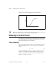
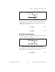
Figure 5-23. Input Impedance Electrical Circuit
Z
in
is the new input impedance. Refer to Appendix A, Specifications, in the
device user manuals at
ni.com/manuals for the input impedance.
Equation 5-20 shows the relationship among all of the resistor values:
(5-20)
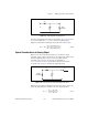
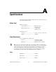
Special Considerations for Analog Output
When you use the circuit shown in Figure 5-19 for AO, the output
impedance changes. Thus, you must choose the values for R
1
and R
2
so that
the final output impedance value is as low as possible. Refer to
Appendix A, Specifications, in the device user manuals at
ni.com/manuals for device specifications. Figure 5-24 shows the
electrical circuit you use to calculate the output impedance.
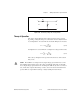
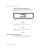
Figure 5-24. Electrical Circuit for Determining Output Impedance
Equation 5-21 shows the relationship between R
1
, R
2
, and Z
out
, where Z
out
is the old output impedance and Z
out2
is the new output impedance:
(5-21)
R
2
V
in
+
–
+
–
R
1
Input
Impedance
Z
in
R
1
R
2
Input Impedance×()
R
2
Input Impedance+()
---------------------------------------------------------+=
R
2
Output
Impedance
R
1
Z
out
Z
out2
Z
out
R
1
+()R
2
×
Z
out
R
1
R
2
++
---------------------------------------=