
Shielded Connector Block User Manual DAQ SCB-68 68-Pin
Chapter 5 Adding Components for Special Functions
© National Instruments Corporation 5-11 SCB-68 Shielded Connector Block User Manual
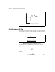
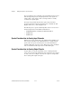
Use Equation 5-3 to design a lowpass filter for a simple resistor and
capacitor circuit, where the values of the resistor and capacitor alone
determine f
c
. In this equation, G is the DC gain and s represents the
frequency domain.
Selecting Components
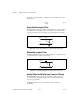
To determine the value of the components in the circuit, fix R (10 kΩ is
reasonable) and isolate C from Equation 5-3 as follows:
(5-4)
The cut-off frequency in Equation 5-4 is f
c
.
For best results, choose a resistor that has the following characteristics:
• Low wattage of approximately 1/8 W
• Precision of at least 5%
• Temperature stability
• Tolerance of 5%
• AXL package (suggested)
• Carbon or metal film (suggested)
Choose a capacitor that has the following suggested characteristics:
• AXL or RDL package
• Tolerance of 20%
• Maximum voltage of at least 25 V
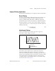
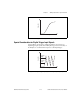
Adding Components
Using the circuit shown in Figure 5-11, you can use a two-component
circuit to build a simple RC filter with analog input, analog output, or
digital input. You can build a single-ended analog input RC filter with pads
F and B for one channel and pads G and D for the next channel. You can
build a differential analog input RC filter with pads F and E.
For TRIG1, you can use pads R1 and RC1. For AO, you can use R2 and
RC2 for DAC1OUT, and you can use R3 and RC3 for DAC0OUT.
C
1
2πRf
c
---------------=