RT Series DAQ Device User Manual RT Series DAQ Device User Manual April 2001 Edition Part Number 322635B-01
Support Worldwide Technical Support and Product Information ni.
Important Information Warranty The RT Series DAQ hardware is warranted against defects in materials and workmanship for a period of one year from the date of shipment, as evidenced by receipts or other documentation. National Instruments will, at its option, repair or replace equipment that proves to be defective during the warranty period. This warranty includes parts and labor.
Compliance FCC/Canada Radio Frequency Interference Compliance* Determining FCC Class The Federal Communications Commission (FCC) has rules to protect wireless communications from interference. The FCC places digital electronics into two classes. These classes are known as Class A (for use in industrialcommercial locations only) or Class B (for use in residential or commercial locations). Depending on where it is operated, this product could be subject to restrictions in the FCC rules.
interference to radio or television reception, which can be determined by turning the equipment off and on, the user is encouraged to try to correct the interference by one or more of the following measures: • Reorient or relocate the receiving antenna. • Increase the separation between the equipment and receiver. • Connect the equipment into an outlet on a circuit different from that to which the receiver is connected. • Consult the dealer or an experienced radio/TV technician for help.
Contents About This Manual Conventions ...................................................................................................................ix Related Documentation..................................................................................................x Chapter 1 Introduction About the RT Series.......................................................................................................1-1 What You Need to Get Started .......................................................
Contents Real-Time Programming ............................................................................................... 4-4 Running a VI at Time-Critical Priority without the RT Development System ................................................................................... 4-4 Use of Shared Memory ................................................................................... 4-4 Configuration Issues .......................................................................................
About This Manual This manual contains information about the RT Series Data Acquisition (DAQ) devices and working with LabVIEW Real-Time (RT). The RT Series DAQ hardware consists of the following devices: • PCI-7030/6040E • PCI-7030/6030E • PCI-7030/6533 • PXI-7030/6040E • PXI-7030/6030E • PXI-7030/6533 The RT Series DAQ family of devices are multifunction I/O boards with an embedded processor.
About This Manual programs, subprograms, subroutines, device names, functions, operations, variables, filenames and extensions, and code excerpts.
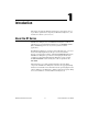
1 Introduction This chapter describes the RT Series DAQ devices, lists what you need to get started, explains how to unpack your RT Series DAQ device, and describes the software you need to use. About the RT Series The RT Series DAQ devices are multifunction DAQ devices with an embedded processor. The RT Series DAQ device, LabVIEW Real-Time (RT), and NI-DAQ provide an easy-to-use system for real-time applications.
Chapter 1 Introduction Table 1-1.
Chapter 1 Introduction Unpacking Your RT Series DAQ device is shipped in an antistatic package to prevent electrostatic damage to the device. Electrostatic discharge can damage several components on the device. To avoid such damage in handling the device, take the following precautions: • Ground yourself by using a grounding strap or by holding a grounded object. • Touch the antistatic package to a metal part of your computer chassis before removing the device from the package.
Installation and Configuration 2 This chapter explains how to install and configure your RT Series DAQ hardware. Installing the Hardware You can install the RT Series DAQ device in any available expansion slot in your computer or PXI chassis. To reduce noise, however, leave as much room as possible between the RT Series DAQ device and other devices and hardware. The following are general installation instructions.
Chapter 2 Installation and Configuration Your RT Series DAQ device is installed. You are now ready to configure your software. PXI Installation Complete the following steps to install your RT Series PXI board. 1. Turn off and unplug your computer. 2. Choose two adjacent unused PXI slots in your system. 3. Remove the filler panels for the slots you have chosen. 4. Insert the RT Series DAQ board into the 5 V PXI slots. Use the injector/ejector handle to fully insert the board into the chassis. 5.
Chapter 2 Installation and Configuration Figure 2-1. Measurement & Automation Explorer Notice that MAX assigns separate device numbers to the PCI/PXI-7030 device and the DAQ daughterboard, as shown in Figure 2-1. The DAQ daughterboard is shown as a separate device under the 7030 processor board. However, the daughterboard has a device number that is different from the 7030 processor board.
Chapter 2 Installation and Configuration daughterboard directly, even though the DAQ daughterboard is configured as a separate device. Only LabVIEW RT applications targeted to the RT Series DAQ device can access the DAQ daughterboard. If you want to test whether the DAQ daughterboard is working, run any DAQ example that ships with LabVIEW RT. Tip To save the configuration information, select Tools»NI-DAQ Configuration»Save Configuration As. Then close MAX. RT Series DAQ Device User Manual 2-4 ni.
3 Hardware Overview This chapter describes the PCI and PXI RT Series DAQ hardware. You can find most of the hardware information you need in your DAQ device user manual. Table 1-1, RT Series DAQ Device and Corresponding DAQ Device Manual, lists the DAQ device user manuals for the RT Series DAQ devices. As shown in Figures 3-1 and 3-2, a DAQ daughterboard attaches to the processor board, and together they form the RT Series DAQ hardware.
Chapter 3 Hardware Overview 1 2 1 Processor Board 2 DAQ Daughterboard Figure 3-2. PXI RT Series Data Acquisition Hardware Processor Board The 7030 processor board contains a microprocessor and support circuitry, as shown in Figure 3-3. The support circuitry includes a chipset with PCI controller and ISA bridge, main memory (DRAM), L2 cache (SRAM), and BIOS. The RT Engine software uses this embedded processor system for its execution platform.
Chapter 3 Hardware Overview Processor Board CPU Embedded CPU Bus BIOS SRAM/DRAM Cache Memory PCI Controller Host PCI Bus Embedded ISA Bus MITE Shared Memory Interface Embedded PCI Bus ISA Bridge Controller BIOS Extension Shared Memory I/O Daughterboard Figure 3-3.
Chapter 3 Hardware Overview DAQ Daughterboard The daughterboard in the RT Series system provides the DAQ functionality. Each daughterboard is a National Instruments DAQ device with some mechanical modifications to allow it to connect to the processor board. You can expect the same high performance and specifications from the daughterboard that you do from the standard version of the device. For example, the PCI/PXI-7030/6040E boards have the same DAQ characteristics as the PXI-6040E.
Chapter 3 Hardware Overview information about how to use the RTSI signals. Table 1-1, RT Series DAQ Device and Corresponding DAQ Device Manual, lists the corresponding manual for each available daughterboard. LEDs The RT Series processor board has two LEDs. You can use these LEDs to indicate the state of your running application. On the PXI-7030 device, the LEDs are visible on the front panel.
4 LabVIEW RT Programming This chapter provides an overview of using LabVIEW Real-Time (RT) and your RT Series DAQ hardware. Targeting LabVIEW RT and Downloading VIs In LabVIEW RT, select Operate»Switch Execution Target to access the Select Target Platform dialog box, shown in Figure 4-1. Figure 4-1. Select Target Platform Dialog Box Use the pull-down menu to select where you want to run VIs.
Chapter 4 LabVIEW RT Programming Select Target Platform dialog box to launch MAX and configure your RT Series DAQ devices. Resetting the RT Series DAQ Device Resetting the RT Series DAQ device is necessary only after you first turn on the system or if communication with the RT Engine cannot be established or has been lost. Also, reset the device when you change the DAQ configuration information for the RT Series DAQ device.
Chapter 4 LabVIEW RT Programming To disable the Select Target Platform dialog box, specify the target platform in the command line argument of your built executable using –target. For example, c:\mybuiltapp_rtengine.exe -target DAQ::3 (for device 3) or to run the application on the host PC, c:\mybuiltapp_host.exe -target host You also can reset the specified device using -reset. For example, c:\mybuiltapp_rtengine.
Chapter 4 LabVIEW RT Programming Real-Time Programming This section provides an overview of real-time programming using your RT Series DAQ hardware. Running a VI at Time-Critical Priority without the RT Development System Instead of using TCP/IP or VI Server to communicate data to a host PC application, you can maximize real-time VI performance on RT Series DAQ devices by peeking and poking data to shared memory.
Chapter 4 LabVIEW RT Programming hardware for these changes to take effect. However, unlike virtual channels, you can set device parameters or accessory configuration information programmatically inside a VI without running MAX. Therefore, you can programmatically change these parameters in your VI without resetting the hardware. Refer to your NI-DAQ documentation and the DAQ section of the LabVIEW Help, available by selecting Help»Contents and Index, for more information about configuration.
A Specifications This appendix lists the specifications of the embedded processor system. Processor Processor ................................................ AMD 486 DX5 32-bit architecture Processor clock speed ............................ 133 MHz CPU bus speed ....................................... 33 MHz Memory .................................................. 8 MB DRAM user-programmable 60 ns, EDO, 5 V, 72-Pin SODIMM On-chip cache ........................................
Appendix A Specifications Power Requirement PCI-7030 only (without daughterboard) .........................1.9 A at +5 VDC (±5%) PXI-7030 only (without daughterboard) .........................2.0 A at +5 VDC (±5%) To calculate the total power requirement, add the processor board requirement from this section to the I/O board requirement given in the I/O board manual. Note Physical Dimensions (Not Including Connectors) PCI-7030.................................................312.9 by 160.5 cm (12.3 by 4.
Technical Support Resources B Web Support National Instruments Web support is your first stop for help in solving installation, configuration, and application problems and questions. Online problem-solving and diagnostic resources include frequently asked questions, knowledge bases, product-specific troubleshooting wizards, manuals, drivers, software updates, and more. Web support is available through the Technical Support section of ni.com NI Developer Zone The NI Developer Zone at ni.
Appendix B Technical Support Resources Worldwide Support National Instruments has offices located around the world to help address your support needs. You can access our branch office Web sites from the Worldwide Offices section of ni.com. Branch office Web sites provide up-to-date contact information, support phone numbers, e-mail addresses, and current events.
Glossary B BIOS basic input/output system—BIOS functions are the fundamental level of any PC or compatible computer. BIOS functions embody the basic operations needed for successful use of the computer hardware resources. bus the group of conductors that interconnect individual circuitry in a computer. Typically, a bus is the expansion vehicle to which I/O or other devices are connected. Examples of PC buses are the ISA and PCI bus.
Glossary device Instrument or controller that is addressable as a single entity and controls or monitors real-world I/O points. A device is often connected to the host computer through some type of communication network or can be a plug-in device. For data acquisition (DAQ) applications, a DAQ device is inside your computer or attached directly to the parallel port of your computer.
Glossary V VISA virtual instrument software architecture—a new driver software architecture developed by National Instruments to unify instrumentation software GPIB, DAQ, and VXI. It has been accepted as a standard for VXI by the VXIplug&play Systems Alliance.
Index B E board configuration, 2-2 to 2-4 bus interface specifications, A-1 embedded applications, 4-2 environment specifications, A-2 executables. See stand-alone executables, creating.
Index processor board, 3-2 to 3-3 board diagram, 3-3 description, 3-2 specifications, A-1 programming. See LabVIEW RT programming. PXI devices. See also hardware overview.
Index S U shared memory host-embedded communication shared memory, A-1 real-time programming, 4-4 software programming choices, 1-3 specifications, A-1 to A-2 stand-alone executables, creating, 4-2 to 4-3 command-line arguments, 4-2 to 4-3 embedded applications, 4-2 system integration, by National Instruments, B-1 unpacking RT Series DAQ devices, 1-3 V VIs downloading VIs, 4-1 to 4-2 RT Series DAQ VIs, 4-5 W Web support from National Instruments, B-1 Worldwide technical support, B-2 T targeting LabVI