
PXI Terminal Block Installation Guide

© National Instruments Corporation 7 NI TB-2709 Installation Guide
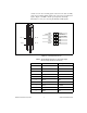
conductors on the other end. The pigtail conductors on the cable assembly
can be used to terminate digital signals to the connector(s) your application
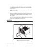
requires. Figure 5 and Table 3 list the pin assignments and wiring
information necessary for connecting the TB-2709 to DIO signals.
Figure 5. 14-Pin Digital I/O Connector
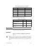
Table 3. TB-2709 Wiring Information for 14-Pos MFIT-Pigtail
Cable Assembly (Part Number 194123-01)
Pin Number Wire Color Signal Name
1 Black D GND
1 Brown D GND
2 Red P0.0
3 Orange P0.1
4 Yellow P0.2
5 Green P0.3
6 Blue CTR 0 OUT
7 Violet D GND
7 Gray D GND
8 White P0.4
Pin 14
Pin 8
Pin 7
Pin 1
14
13
12
11
10
9
8
7
6
5
4
3
2
1
PFI 9
CTR 1 OUT
CHASSIS GND
P0.7
P0.6
P0.5
P0.4
GND
CTR 0 OUT
P0.3
P0.2
P0.1
P0.0
GND