PXI PXI-PCI 8330 Series User Manual MXI-3 Multi-System Extension Interface for PCI, CompactPCI, and PXI Bus Computers PXI-PCI 8330 Series User Manual September 1999 Edition Part Number 370103A-01
Worldwide Technical Support and Product Information www.natinst.
Important Information Warranty The PXI-PCI 8330 Series hardware is warranted against defects in materials and workmanship for a period of one year from the date of shipment, as evidenced by receipts or other documentation. National Instruments will, at its option, repair or replace equipment that proves to be defective during the warranty period. This warranty includes parts and labor.
Compliance FCC/DOC Radio Frequency Interference Class A Compliance This equipment generates and uses radio frequency energy and, if not installed and used in strict accordance with the instructions in this manual, may cause interference to radio and television reception. Classification requirements are the same for the Federal Communications Commission (FCC) and the Canadian Department of Communications (DOC).
Contents About This Manual Conventions ...................................................................................................................vii Related Documentation..................................................................................................viii Chapter 1 Introduction About the MXI-3 System...............................................................................................1-1 Description and Features ............................................................
Contents Appendix A Specifications Appendix B Technical Support Resources Glossary Index Figure Figure 2-1. Figure 2-2. Installing the PCI MXI-3 ...................................................................... 2-3 PXI MXI-3 Before Installation ............................................................. 2-5 Figure 3-1. Figure 3-2. Figure 3-3. MXI-3 Block Diagram .......................................................................... 3-2 Basic MXI-3 Configurations...............................
About This Manual This manual describes the features, functions, and operation of the PXI-PCI 8330 Series. The four products in this series are the PCI-8330, the PXI-8330, the PCI-8335, and the PXI-8335. The PXI-PCI 8330 Series incorporates MXI-3 technology, which couples two physically separate PCI, CompactPCI, or PXI buses with either a copper or fiber-optic data link capable of 1.5 Gbytes/s serial data rates.
About This Manual Related Documentation The following documents contain information that you might find helpful as you read this manual: PXI-PCI 8330 Series User Manual • Set Up Your MXI-3 System • Your computer or chassis documentation • PXI Specification, revision 1.0 • PCI Specification, revision 2.2 • PCI-PCI Bridge Architecture Specification, revision 1.0 • PICMG CompactPCI 2.0 R2.1 specification • PXI chassis and documentation (PXI bus systems only) viii www.natinst.
1 Introduction This chapter describes the PXI-PCI 8330 Series, lists what you need to get started, and explains how to unpack and set up your hardware. The four products in this series are the PCI-8330, the PXI-8330, the PCI-8335, and the PXI-8335. The PXI-PCI 8330 Series incorporates MXI-3 technology. The terms MXI-3, MXI-3 card and MXI-3 system in this manual refer to both the PCI MXI-3 and PXI MXI-3 cards and systems, unless otherwise noted.
Chapter 1 Introduction Software Transparency Because the MXI-3 system is a PCI-PCI bridge, all devices on the system appear as local devices to the primary computer. You do not need to rewrite your device drivers for operation on a MXI-3 system. High Performance MXI-3 supports write posting and read prefetching to enhance performance, and provides clock distribution and bus arbitration for up to seven slots on each secondary bus.
Chapter 1 3. Caution Introduction Remove the device from the package and inspect the device for loose components or any other signs of damage. Notify National Instruments if the device appears damaged in any way. Do not install a damaged device in your computer. Never touch the exposed pins of connectors. Doing so may damage the device.
2 Installation This chapter explains how to install the MXI-3 software and hardware. Software Installation Your MXI-3 kit includes a setup program for Microsoft Windows operating system. The setup program works in the same manner for Windows NT, 98, and 95. Users of other operating systems can ignore this section. Note The software included for Microsoft Windows is provided so that the performance of National Instruments PXI modules is optimized across a PCI-PCI bridge.
Chapter 2 Installation Hardware Installation You can install a MXI-3 card in any available PCI expansion slot in your PC. The following are general instructions for installing the PCI MXI-3 and PXI MXI-3 cards. Consult your computer user manual or technical reference manual for specific instructions and warnings. Installing a PCI MXI-3 Card 1. Plug in but do not turn on your computer before installing the PCI MXI-3 device.
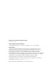
Chapter 2 Installation 4 3 2 1 1 2 PCI Bus Slot Cut-Outs 3 4 PCI Bus Card-Edge Connector PCI MXI-3 Board Figure 2-1. Installing the PCI MXI-3 Installing a PXI MXI-3 Card You can install the PXI MXI-3 in any available 5 V slot in your PXI or CompactPCI chassis. 1. Turn off your PXI or CompactPCI chassis, but leave it plugged in while installing the PXI MXI-3 card. The power cord grounds the chassis and protects it from electrical damage while you install the module. 2.
Chapter 2 Installation 3. Remove or open any doors or covers blocking access to the system controller slot (Slot 1) in the mainframe. 4. Touch the metal part of the case to discharge any static electricity that might be on your clothes or body. 5. Make sure the injector/ejector handle is in its downward position. Align the PXI MXI-3 card with the card guides on the top and bottom of the system controller slot. Do not raise the injector/ejector handle as you insert the PXI MXI-3 card.
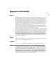
Chapter 2 Installation PXI/CompactPCI Chassis ON PXI MXI-3 STA ND BY 1 2 3 4 5 6 PXI/CompactPCI Slot 1 7 8 Ejector Handle in Down Position Figure 2-2. PXI MXI-3 Before Installation Cabling 1. Connect the appropriate serial cable to both primary and secondary MXI-3 cards. If you are using a fiber-optic cable, be sure to remove the protective caps from the connectors. Caution Do not remove the cable after the system is powered on. Doing so may crash the system. 2.
3 Hardware Overview This chapter presents an overview of the hardware functions of your MXI-3 system, and explains the operation of each functional unit. Functional Overview The MXI-3 system is a PCI-PCI bridge that needs no software for normal operation. When the desktop PC or the CompactPCI/PXI controller powers on, the system BIOS scans its local PCI bus for devices.
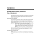
Chapter 3 Hardware Overview C P P P X C C I I I B u s Parallelto-Serial Converter Transmitter Port PCI/PXI Interface Port Serial Data Copper/ Fiber-Optic Transceiver Serialto-Parallel Converter Receiver Port Serial Data Figure 3-1.
Chapter 3 Hardware Overview PC to PXI/CompactPCI PXI/CompactPCI to PXI/CompactPCI Figure 3-2. Basic MXI-3 Configurations Because MXI-3 complies with the standard PCI-to-PCI bridging specification, it can take advantage of a variety of other extension configurations. Figure 3-3, Additional MXI-3 Configurations, shows how MXI-3 can be used to daisy-chain multiple systems in row, all under the control of the primary system, in this case a PC.
Chapter 3 Hardware Overview Star configurations are also possible using MXI-3 interfaces in the primary system to fine tune performance. Daisy-Chain Configuration Star Configuration Figure 3-3. Additional MXI-3 Configurations Functional Unit Descriptions National Instruments MXI-3 ASIC The MXI-3 ASIC, which contains most of the design of the two-board system, is a PCI master/slave device using the PCI-PCI bridge register set.
Chapter 3 Hardware Overview Serial Transmitter The serial transmitter is a parallel-to-serial data converter. The parallel-to-serial converter serializes the 20-bit wide parallel data from the MXI-3 ASIC and sends it to the transceiver. Serial Receiver The serial receiver is a serial-to-parallel data converter. The serial-to-parallel converter deserializes the data from the receiver and supplies the 20-bit wide parallel data to the MXI-3 ASIC.
Chapter 3 Hardware Overview Table 3-1. National Instruments MXI-3 Cables Cable length (meters) Description 2m MXI-3 copper cable 5m MXI-3 copper cable 10 m MXI-3 copper cable 30 m MXI-3 fiber optic cable If you require lengths greater than 30 meters in fiber optic cable, contact Molex, cable vendor for National Instruments. Table 3-2 describes Molex cables. The fiber-optic cable offered by Molex is a multimode, 62.5/125 µm cable with a duplex, zipcord, 3.0 × 6.5 mm, OFNR cable construction.
A Specifications This appendix lists the system specifications for PCI MXI-3 and PXI MXI-3 cards. These specifications are typical at 25 °C, unless otherwise stated. Physical Dimensions PCI .................................................. 10.7 by 17.5 cm (4.2 by 6.9 in.) PXI .................................................. 10.0 by 16.0 cm (3.9 by 6.3 in.) Available cable lengths Copper............................................. 2 m, 5 m, 10 m, 20 m Fiber-optic.......................................
Technical Support Resources B This appendix describes the comprehensive resources available to you in the Technical Support section of the National Instruments Web site and provides technical support telephone numbers for you to use if you have trouble connecting to our Web site or if you do not have internet access. NI Web Support To provide you with immediate answers and solutions 24 hours a day, 365 days a year, National Instruments maintains extensive online technical support resources.
Appendix B Technical Support Resources Software-Related Resources • Instrument Driver Network—A library with hundreds of instrument drivers for control of standalone instruments via GPIB, VXI, or serial interfaces. You also can submit a request for a particular instrument driver if it does not already appear in the library. • Example Programs Database—A database with numerous, non-shipping example programs for National Instruments programming environments.
Glossary Prefix Meaning Value n- nano- 10 –9 µ- micro- 10 – 6 m- milli- 10 –3 c- centi- 10 –2 k- kilo- 10 3 M- mega- 10 6 Symbols ° Degrees ≥ Equal or greater than ≤ Equal or less than % Percent A ASIC Application-Specific Integrated Circuit—a proprietary semiconductor component designed and manufactured to perform a set of specific functions for a specific customer B bus the group of conductors that interconnect individual circuitry in a computer.
Glossary C C Celsius clock hardware component that controls timing for reading from or writing to groups counter/timer a circuit that counts external pulses or clock pulses (timing) D device a plug-in instrument card or pad that can contain multiple channels and conversion devices. Plug-in boards and PCMCIA cards, which connects to your computer parallel port, are examples of devices.
Glossary PCI-MITE A custom ASIC designed by National Instruments that implements the PCI bus interface. The PCI-MITE supports bus mastering for high speed data transfers over the PCI bus. It is also used in PXI cards. PCI-PCI bridge A device that transparently expands the PCI bus on a computer motherboard to another bus segment in the same machine. The bridge expands the number of PCI expansion slots, but remains transparent to the end user. PXI Stands for PCI eXtensions for Instrumentation.
Index A H additional MXI-3 configurations (figure), 3-4 ASIC, 3-4 HSSDC (High Speed Serial Data Connector Cable), 3-5 HSSDC (High Speed Serial Data Connector Receptacle), 3-5 B basic MXI-3 configurations (figure), 3-3 block diagram, 3-2 I installation cable options, 3-5 cabling, 2-5 hardware, 2-2 of a PCI MXI-3 card, 2-2 of a PXI MXI-3 card, 2-3 software, 2-1 C cable options, 3-5 chassis expansion, 3-2 configuration, basic (figure), 3-3 configurations, additional daisy chain (figure), 3-4 star (figure
Index O S online problem-solving and diagnostic resources, B-1 overview functional unit descriptions, 3-4 hardware, 3-1 MXI-3 block diagram, 3-2 serial receiver, 3-5 serial transmitter, 3-5 software, 2-1 software transparency, 1-2 software-related resources, B-2 specifications, A-1 P T PCI MXI-3 card installation, 2-2 installation (figure), 2-3 PCI-PCI bridge, 1-2 PXI MXI-3 card installation, 2-3 installation (figure), 2-5 technical support resources, B-1 telephone support, B-2 W Web support from N