PXI NI 8171 Series User Manual NI 8171 Series User Manual August 2001 Edition Part Number 370382A-01
Support Worldwide Technical Support and Product Information ni.
Important Information Warranty The NI 8171 series of embedded PXI computers are warranted against defects in materials and workmanship for a period of one year from the date of shipment, as evidenced by receipts or other documentation. National Instruments will, at its option, repair or replace equipment that proves to be defective during the warranty period. This warranty includes parts and labor.
Compliance FCC/Canada Radio Frequency Interference Compliance* Determining FCC Class The Federal Communications Commission (FCC) has rules to protect wireless communications from interference. The FCC places digital electronics into two classes. These classes are known as Class A (for use in industrial-commercial locations only) or Class B (for use in residential or commercial locations). Depending on where it is operated, this product could be subject to restrictions in the FCC rules.
Canadian Department of Communications This Class B digital apparatus meets all requirements of the Canadian Interference-Causing Equipment Regulations. Cet appareil numérique de la classe B respecte toutes les exigences du Règlement sur le matériel brouilleur du Canada. Compliance to EU Directives Readers in the European Union (EU) must refer to the Manufacturer’s Declaration of Conformity (DoC) for information** pertaining to the CE Mark compliance scheme.
Contents About This Manual How to Use the Documentation Set...............................................................................xi Conventions ...................................................................................................................xi Related Documentation..................................................................................................xii Chapter 1 Introduction Benefits of PXI ..............................................................................
Contents Upgrading RAM............................................................................................................ 2-13 Hard Drive Recovery..................................................................................................... 2-14 Recovery from a CD-ROM............................................................................. 2-14 Recovery from a Network............................................................................... 2-15 Installing an OS ...................
Contents Appendix A Specifications Appendix B Technical Support Resources Glossary Index © National Instruments Corporation ix NI 8171 Series User Manual
About This Manual This manual contains detailed instructions for installing and configuring your National Instruments NI 8171 series embedded computer kit. The NI 8171 series includes the NI 8176, NI 8175, and NI 8174 embedded PXI computers. How to Use the Documentation Set Begin by reading the NI 8171 Series Installation Guide, a brief quick-start guide that describes how to install and get started with your controller.
About This Manual Related Documentation The following documents contain information you may find helpful as you read this manual: NI 8171 Series User Manual • PICMG 2.0 R2.1 CompactPCI Specification, PCI Industrial Computers Manufacturers Group • IEEE Standard P1284.1-1997 (C/MM) Standard for Information Technology for Transport Independent Printer/System Interface • PCI Local Bus Specification, Revision 2.2, PCI Special Interest Group • PXI Specification, Revision 2.
1 Introduction Benefits of PXI The PXIbus specification defines a compact modular PC platform for industrial instrumentation. PXI leverages the PCI bus, which is the de facto standard for today’s desktop computer software and hardware designs. As a result, PXI users receive all the benefits of PCI within an architecture that supports mechanical, electrical, and software features tailored to industrial instrumentation, data acquisition, and automation applications.
Chapter 1 Introduction Modules The NI 8171 series includes three configurations: the NI 8176, NI 8175, and NI 8174. All three modules have a standard I/O set, and some modules include additional I/O connections. The standard I/O on all modules includes video, RS-232 serial port, parallel port, two USB ports, 10/100 ENET, PS/2 mouse and keyboard port, Reset button, and PXI Trigger. The modules have the following configurations: • The NI 8176 has a 1.
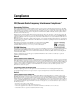
Chapter 1 Introduction Socket 370 CPU VGA Connector Chip Set Graphics Memory Controller Hub SO-DIMM SDRAM PC 133 PXI-1020 PXI-1025 TFT LCD Interface Hub Interface ATA 100 IDE Interface Chip Set I/O Controller Hub 2 USB Connectors PXI-1020/1025 Interface/ USB to PS/2 10/100BaseT Ethernet Flash ROM PXI Connector PCI Bus PXI Triggers LPC Bus LPT 1 COM 1 COM 2 SMB to PXI Trigger Super I/O XBus PCI BUS Watchdog Internal Floppy PS/2 Keyboard/ Mouse SMB Figure 1-1.
Chapter 1 Introduction The NI 8171 series consists of the following logic blocks on the CPU module and the I/O (daughter card) module. The CPU module has the following logic blocks: NI 8171 Series User Manual • Socket 370 CPU is the socket definition for the Intel Pentium III processor families. • The SO-DIMM block consists of a 64-bit SDRAM socket that can hold up to 256 MB. • The Chip Set GMCH connects to the CPU, SDRAM, and video.
Chapter 1 Introduction National Instruments Software National Instruments has developed several software kits you can use with the NI 8171 series. The software is already installed on your hard drive. NI-DAQ has an extensive library of functions that you can call from your application programming environment.
Chapter 1 Introduction NI 8171 Series User Manual • LabWindows/CVI is an interactive ANSI C programming environment designed for building virtual instrument applications. LabWindows/CVI delivers a drag-and-drop editor for building user interfaces, a complete ANSI C environment for building your test program logic, and a collection of automated code generation tools, as well as utilities for building automated test systems, monitoring applications, or laboratory experiments.
Installation and Configuration 2 This chapter contains information about installing and configuring your NI 8171 series controller. Installing the NI 8171 Series This section contains general installation instructions for the NI 8171 series. Consult your PXI chassis user manual for specific instructions and warnings. 1. Plug in your chassis before installing the NI 8171 series. The power cord grounds the chassis and protects it from electrical damage while you install the module.
Chapter 2 Installation and Configuration 8. Check the installation. 9. Connect the keyboard and mouse to the appropriate connectors. If you are using a PS/2 keyboard and a PS/2 mouse, use the Y-splitter adapter (see Figure 4-1, Y-Splitter Cable) included with your controller to connect both to the PS/2 connector. 10. Connect the VGA monitor video cable to the VGA connector. 11. Connect devices to ports as required by your system configuration. 12. Power on the chassis. 13.
Chapter 2 Installation and Configuration How to Remove the Controller from the PXI Chassis The NI 8171 series controllers are designed for easy handling. To remove the unit from the PXI chassis: 1. Turn off power. 2. Remove the bracket-retaining screws in the front panel. 3. Press the injector/ejector handle down. 4. Slide the unit out of the chassis. BIOS Setup You can change the NI 8171 series configuration settings in the BIOS setup.
Chapter 2 Installation and Configuration • Up Arrow, Down Arrow—Use these keys to move between the options within a setup menu. (To use the arrows on the numeric keypad, you must turn off Num Lock.) • —Use this key to either enter a submenu or display all available settings for a highlighted configuration option. • —Use this key to return the parent menu of a submenu. At the top-level menus, this key serves as a shortcut to the Exit menu.
Chapter 2 Installation and Configuration DMI Event Logging Submenu Major errors that occur during the BIOS booting process are stored in battery-backed memory on the controller, and remain there until you view and clear them using this submenu. This logging capability allows a system administrator to detect the historical occurrence of faults on a controller.
Chapter 2 Installation and Configuration of supporting two ATA devices (Master and Slave). Use this setting to disable one or more of these integrated channels. You should modify this setting only if specified in other sections of this manual. The default is Both. • Write Protect Boot Sector—When set to Yes, this setting prevents modification of a hard disk boot sector via INT 13h services, which may help prevent certain computer viruses from infecting the controller.
Chapter 2 Installation and Configuration specialized external floppy drive. Normally, using a Universal Serial Bus (USB) floppy drive is preferable to this option, which requires a specially designed drive and cable. (See the Parallel Port section in Chapter 3, I/O Information, for pinout information.) Setting this option to Parallel Port disables normal LPT1 functionality. The Default is Enabled, which routes the signals to the standard internal floppy drive.
Chapter 2 Installation and Configuration Security Setup Menu Use this menu to apply system-level passwords to the NI 8171 series controller. With these passwords, you can restrict access to the BIOS setup program, floppy drives, and operating systems installed on bootable devices. If you forget any password, you can restore the CMOS contents to the factory default as described in the System CMOS section of this manual.
Chapter 2 Installation and Configuration • Hard Drive—The boot list includes all IDE/ATA hard disks detected on the system. Press on this entry to expand it to select the boot priority of individual IDE/ATA hard drives. • CD-ROM Drive—The boot list includes all classes of CD-ROM drive, including USB drives and IDE/ATA drives integrated into a PXI-1020 or PXI-1025 chassis. • Network Boot—This option is for National Instruments controllers with PXE ROM.
Chapter 2 Installation and Configuration System CMOS The NI 8171 series contains a backed-up memory used to store BIOS configuration information. To clear the CMOS contents: Caution 1. Turn off power. 2. Remove the controller from the chassis. 3. Move the jumper on J1 from pins 1-2 to pins 2-3 as shown in Figure 2-2. 4. Wait 1 second. Move the jumper back to pins 1-2. 5. Reinstall the controller in the chassis. Do not leave the jumper on pins 2-3. Doing so decreases battery life.
Chapter 2 Installation and Configuration Using the Controllers with PXI-1020 and PXI-1025 Chassis The NI 8176 and NI 8175 controllers interface directly to the National Instruments PXI-1020 and PXI-1025 chassis. The interface contains signals to interface to the chassis LCD display, IDE CDROM drive, and PS2 mouse and keyboard. LCD Display To enable/disable the LCD display for a PXI-1020 or PXI-1025 chassis: 1. Install the controller in a PXI-1020 or PXI-1025 chassis. 2.
Chapter 2 Installation and Configuration Chassis Mouse and Keyboard The PXI-1020 has an integrated PS/2 mouse. The PXI-1025 has an integrated PS/2 keyboard and mouse. To simplify configuration for these chassis, the NI 8171 series includes an internal USB-to-PS/2 adapter. When the NI 8171 series is installed in a PXI-1020 or PXI-1025 chassis, the USB-to-PS/2 adapter is enabled automatically.
Chapter 2 Installation and Configuration PXI Features PXI Trigger Connectivity The SMB connector on the NI 8171 series front panel can connect to or from any PXI backplane trigger line through software. A trigger allocation process is needed to prevent two resources from connecting to the same trigger line, resulting in the trigger being double-driven and possibly damaging the hardware.
Chapter 2 Installation and Configuration 1 2 1 SO-DIMM Module 2 SO-DIMM Socket Figure 2-3. Installing a SO-DIMM in an NI 8171 Series Controller Hard Drive Recovery The NI 8171 series controllers include a recovery CD. There are two methods for recovering the hard disk to its original state. Recovery from a CD-ROM These steps apply to a USB CD-ROM, IDE CD-ROM (when using a PXI-1020 or PXI-1025 chassis), or SCSI CD-ROM drive (when a SCSI adapter is installed).
Chapter 2 3. Installation and Configuration The BIOS boots from CD-ROM drive. Follow the prompts to recover the hard drive. Not all CD-ROMs are bootable with the NI 8171 series controllers. For a complete list of USB CD-ROM drives that National Instruments has verified as bootable, see ni.com/support/pxisupp.htm. Note Recovery from a Network To recover the hard disk from a network: 1. Create a DOS boot disk with network support.
Chapter 2 Installation and Configuration Installing from a Network To install an OS from a network: NI 8171 Series User Manual 1. Create a DOS boot disk with network support. (The DOS network drivers and a network boot disk example are on the recovery CD.) 2. Use another PC on the network with a CD-ROM drive. Share the drive and load the OS installation CD. 3. Boot the NI 8171 series using the network boot disk. 4. Run the net utility from the a drive. Map the shared CD-ROM drive. 5.
3 I/O Information Front Panel Connectors Table 3-1 lists various peripherals and their corresponding NI 8171 series external connectors, bus interfaces, and functions. Table 3-1.
Chapter 3 I/O Information VGA Figure 3-1 shows the location and pinouts for the VGA connector on the NI 8171 series. Table 3-2 lists and describes the VGA connector signals. AMP manufactures a mating connector with part numbers 748364-1 (housing) and 748333-2 (pin contact). 11 6 1 VGA 15 10 5 Figure 3-1. VGA Connector Location and Pinout Table 3-2.
Chapter 3 I/O Information Table 3-2. VGA Connector Signals (Continued) Pin Signal Name Signal Description 11 NC Not Connected 12 SD Serial Data 13 HSync Horizontal Sync 14 VSync Vertical Sync 15 SC Serial Clock COM1 and COM2 Figure 3-2 shows the location and pinouts for the COM1 and COM2 connectors on the NI 8171 series. Table 3-3 lists and describes the COM1 and COM2 connector signal. AMP manufactures a serial port mating connector, part number 745491-5.
Chapter 3 I/O Information Table 3-3. COM1 and COM2 Connector Signals (Continued) Pin Signal Name Signal Description 4 DTR* Data Terminal Ready 5 GND Ground 6 DSR* Data Set Ready 7 RTS* Ready to Send 8 CTS* Clear to Send 9 RI* Ring Indicator Ethernet Figure 3-3 shows the location and pinouts for the Ethernet connector on the NI 8171 series. Table 3-4 lists and describes the Ethernet connector signals. AMP manufactures a mating connector, part number 554739-1.
Chapter 3 I/O Information Table 3-4. Ethernet Connector Signals Pin Signal Description 1 Differential Transmit 2 Differential Transmit 3 Differential Receive 4 NC 5 NC 6 Differential Receive 7 NC 8 NC Parallel Port Figure 3-4 shows the location and pinouts for the IEEE 1284 (parallel) connector on the NI 8171 series. Table 3-5 lists and describes the IEEE 1284 connector signals. AMP manufactures a parallel port compatible connector, part number 747052-2.
Chapter 3 I/O Information Table 3-5.
Chapter 3 I/O Information Universal Serial Bus Figure 3-5 shows the location and pinouts for the Universal Serial Bus (USB) connector on the NI 8171 series. Table 3-6 lists and describes the USB connector signals. AMP manufactures a USB mating connector, part number 787633. 4 1 USB Figure 3-5. USB Connector Location and Pinout Table 3-6.
Chapter 3 I/O Information PS/2 Figure 3-6 shows the location and pinouts for the PS/2 connector on the NI 8171 series. Table 3-7 lists and describes the PS/2 connector signals. To connect both a PS/2 keyboard and PS/2 mouse to the NI 8171 series, use the Y-splitter adapter cable (see Figure 4-1 in Chapter 4, Common Configuration Questions) included with your controller. 5 3 1 PS/2 2 6 4 Figure 3-6. PS/2 Connector Location and Pinout Table 3-7.
Chapter 3 I/O Information Trigger The TRG connector is the software-controlled trigger connection for routing PXI triggers to or from the backplane trigger bus. Figure 3-7 shows the TRG connector location on the NI 8171 series. Table 3-8 lists and describes the trigger connector signals. 2 1 Figure 3-7. TRG Connector Location and Pinout Table 3-8.
Chapter 3 I/O Information GPIB (IEEE 488.2) Figure 3-8 shows the location and pinouts for the GPIB connector on the NI 8171 series. Table 3-9 lists and describes the GPIB connector signals. AMP manufactures a GPIB mating connector, part number 554349-01. 24 12 13 1 GPIB Figure 3-8. GPIB Connector Location and Pinout Table 3-9.
Chapter 3 I/O Information Table 3-9.
Chapter 3 I/O Information PXI-1020 and PXI-1025 Chassis Interface The NI 8176 and NI 8175 controllers interface directly to following devices on the National Instruments PXI-1020 and PXI-1025 chassis: • IDE CD-ROM • Integrated mouse and keyboard via integrated USB-to-PS2 adapter • LCD display For more information, see the Using the Controllers with PXI-1020 and PXI-1025 Chassis section in Chapter 2, Installation and Configuration. NI 8171 Series User Manual 3-12 ni.
Common Configuration Questions 4 This chapter answers common configuration questions you may have when using the NI 8171 series embedded controller. General Questions What do the LEDs on the NI 8171 series front panel mean? The green LED indicates the power supplies to/on the NI 8171 series are within spec. The supplies monitored are 3.3 V, 5 V, +12 V, and the internally regulated processor core voltage. The hard drive LED lights when there is hard drive activity on the NI 8171 series.
Chapter 4 Common Configuration Questions • An external USB mass storage device such as a USB hard drive or CD-ROM. • An external USB floppy drive. Note There are some limitations when booting from a USB device. Windows does not support booting from USB devices. The NI 8171 series BIOS configures the USB devices so they will work in a DOS environment. Due to the Windows limitation, you also cannot install the OS from a USB CD-ROM.
Chapter 4 Common Configuration Questions What if I don’t have a Y-splitter cable? Can I still use a mouse and keyboard? If you do not have a Y-splitter cable, plug a PS/2 keyboard into the PS/2 combo connector. However, you cannot use a PS/2 mouse without the Y-splitter, so use a serial or USB mouse. How do I connect a standard 25-pin LPT cable to the NI 8171 series? The NI 8171 series uses a type C LPT connector. Most parallel port devices use a type A connector.
Chapter 4 Common Configuration Questions • SCSI, LPT, or PC card-based CD-ROM—Other types of CD-ROM drives are available. Check with the vendor to make sure Windows 2000 supports the drive. • Mapped network drive—You can use the Ethernet to connect to another computer. If you share the CD-ROM drive on the other computer, you can map the shared CD-ROM drive to a drive letter on the NI 8171 series.
Chapter 4 Common Configuration Questions 4. Map the shared CD-ROM drive to K:. 5. Run k:\recover.bat. Follow the prompts to recover the hard drive. Chassis Configuration How do I set up the NI 8171 series to work with a PXI-1020 or PXI-1025 chassis? The NI 8176 and NI 8175 controllers interface directly to the National Instruments PXI-1020 and PXI-1025 chassis. The interface contains signals to interface to the chassis LCD display, IDE CDROM drive, and PS/2 mouse and keyboard.
Chapter 4 Common Configuration Questions Chassis Mouse and Keyboard The PXI-1020 has an integrated PS/2 mouse. The PXI-1025 has an integrated PS/2 keyboard and mouse. To simplify the configuration for these chassis, the NI 8171 series includes an internal USB-to-PS/2 adapter. When the NI 8171 series is installed in a PXI-1020 or PXI-1025 chassis, the USB-to-PS/2 adapter is enabled automatically.
Chapter 4 Common Configuration Questions 1 2 1 SO-DIMM Module 2 SO-DIMM Socket Figure 4-2. Installing a SO-DIMM in an NI 8171 Series Controller How do I flash a new BIOS? You need to download the new BIOS from ni.com/support/pxisupp.htm. To download the new BIOS, follow the instructions on the Web site. Where do I get the latest software drivers? You can download the latest drivers from ni.com/support/pxisupp.htm. My NI 8174 does not have an internal floppy drive.
Chapter 4 Common Configuration Questions The LPT port on the NI 8171 series can also be configured through the BIOS setup for floppy signals instead of LPT signals. See Chapter 3, I/O Information, for the floppy drive pinout. Windows NT4 Issues Does Windows NT4 support USB and plug and play? National Instruments recommends using a USB CD-ROM for software installation when using Windows 2000. However, Windows NT4 does not natively support USB.
5 Troubleshooting This chapter answers common troubleshooting questions you may have when using the NI 8171 series embedded computer. What if the NI 8171 series does not boot? Several problems can cause a controller not to boot. Here are some things to look for and possible solutions. Things to Notice • Which LEDs come on? The Power OK LED should stay lit. The Drive LED should blink during boot as the disk is accessed.
Chapter 5 Troubleshooting My controller boots fine until I get to Windows, at which point I cannot read the screen. This may include garbled output, white screen, black screen, or an out of synch message from the monitor. This problem usually results from having the video card output set past the limits of the monitor. You will need to boot Windows in Safe Mode. To do this, reboot the controller. As Windows begins to boot, hold down . For Windows NT, select Windows NT (VGA MODE) from the boot manager.
Chapter 5 Troubleshooting I can’t change the display on the NI 8171 series controller from 640 × 480 to 800 × 600. What’s wrong? If you are using a PXI-1020 or PXI-1025 chassis, the integrated LCD limits the maximum resolution displayed. If you are not using a PXI-1020 or PXI-1025 chassis, be sure the video driver is installed. If it is not, see the Drivers.txt file on the hard drive or recovery CD-ROM. What if there is a power loss during a BIOS update? Create a crisis recovery disk. Unzip crisis.
A Specifications This appendix lists the electrical, mechanical, and environmental specifications of the NI 8171 series embedded computers. NI 8176 Electrical Current (A) Voltage (V) Typical Maximum +3.3 3A 4A +5 3.8 A 6A +12 0.01 A 0.05 A –12 0A 0A Physical Board dimensions................................... PXI 3U-size module 8.1 by 13 by 21.6 cm (3.2 by 5.1 by 8.5 in.) Slot requirements ...................................
Appendix A Specifications Environmental Temperature............................................0° to 50° C operating –20° to 65° C storage Relative humidity ...................................10% to 90% noncondensing, operating 5% to 95% noncondensing, storage EMI .........................................................FCC Class A verified, EC verified Functional shock.....................................30 g peak, half-sine, 11 ms pulse Random vibration ...................................5 to 500 Hz, 0.
Appendix A Specifications Physical Board dimensions................................... PXI 3U-size module 8.1 by 13 by 21.6 cm (3.2 by 5.1 by 8.5 in.) Slot requirements ................................... One system slot plus three controller expansion slots Compatibility ......................................... Fully compatible with PXI specification MTBF..................................................... 180,000 h Weight .................................................... 1.07 Kg (2.
Appendix A Specifications NI 8174 Electrical Current (A) Voltage (V) Typical Maximum +3.3 3A 4.3 A +5 2A 3.5 A +12 0.01 A 0.05 A –12 0A 0A Physical Board dimensions ...................................PXI 3U-size module 6.1 by 13 by 21.6 cm (2.4 by 5.1 by 8.5 in.) Slot requirements ....................................One system slot plus three controller expansion slots Compatibility ..........................................Fully compatible with PXI specification MTBF ......................
Appendix A Specifications Random vibration................................... 5 to 500 Hz, 0.3 grms, operating 5 to 500 Hz, 2.4 grms, nonoperating For full EMC compliance, you must operate this device with shielded cabling. In addition, all covers and filler panels must be installed. Refer to the Declaration of Conformity (DoC) for this product for any additional regulatory compliance information. To obtain the DoC for this product, click Declaration of Conformity at ni.com/hardref.nsf/.
Technical Support Resources B Web Support National Instruments Web support is your first stop for help in solving installation, configuration, and application problems and questions. Online problem-solving and diagnostic resources include frequently asked questions, knowledge bases, product-specific troubleshooting wizards, manuals, drivers, software updates, and more. Web support is available through the Technical Support section of ni.com. NI Developer Zone The NI Developer Zone at ni.
Appendix B Technical Support Resources Worldwide Support National Instruments has offices located around the world to help address your support needs. You can access our branch office Web sites from the Worldwide Offices section of ni.com. Branch office Web sites provide up-to-date contact information, support phone numbers, e-mail addresses, and current events.
Glossary Prefix Meaning Value n- nano- 10 –9 µ- micro- 10 – 6 m- milli- 10 –3 k- kilo- 10 3 M- mega- 10 6 G- giga- 10 9 t- tera- 10 12 Symbols ° degrees Ω ohms % percent A A amperes AC Alternating Current ASIC application-specific integrated circuit B B bytes backplane An assembly, typically a printed circuit board, with connectors and signal paths that bus the connector pins.
Glossary BIOS Basic Input/Output System. BIOS functions are the fundamental level of any PC or compatible computer. BIOS functions embody the basic operations needed for successful use of the computer’s hardware resources.
Glossary embedded controller An intelligent CPU (controller) interface plugged directly into the PXI backplane, giving it direct access to the PXI bus. It must have all of its required PXI interface capabilities built in. EMC Electromagnetic Compatibility EMI electromagnetic interference EPP Enhanced Parallel Port expansion ROM An onboard EEPROM that may contain device-specific initialization and system boot functionality F FCC Federal Communications Commission G g 1. grams 2.
Glossary instrument driver A set of routines designed to control a specific instrument or family of instruments, and any necessary related files for LabWindows/CVI or LabVIEW interrupt A means for a device to request service from another device interrupt level The relative priority at which a device can interrupt I/O input/output; the techniques, media, and devices used to achieve communication between machines and users IRQ* Interrupt signal ISA Industry Standard Architecture; the original PC b
Glossary N NI-488 or NI-488.2 The National Instruments software for GPIB systems NI-DAQ The National Instruments software for data acquisition instruments NI-VISA The National Instruments implementation of the VISA standard; an interface-independent software that provides a unified programming interface for VXI, GPIB, and serial instruments NMI Non-maskable interrupt; high-priority interrupt that cannot be disabled by another interrupt.
Glossary RMS Root mean squared. See gRMS.
Index A common configuration questions boot options, 4-1 cables and connections, 4-2 chassis configuration, 4-5 driver installation, 4-3 general questions, 4-1 hard drive recovery, 4-4 operating system, 4-3 PXI configuration, 4-8 upgrade information, 4-6 Windows NT4, 4-8 CompactPCI specification, 1-1 ComponentWorks, 1-6 ComponentWorks++, 1-6 configuration common questions boot options, 4-1 cables and connections, 4-2 chassis configuration, 4-5 driver installation, 4-3 general questions, 4-1 hard drive reco
Index G Universal Serial Bus (USB) connector and signals, 3-7 VGA connector and signals, 3-2 conventions used in the manual, xi customer education, B-1 GPIB (IEEE 488.2), 3-10 connector location and pinout (figure), 3-10 connector signals (table), 3-10 driver installation, 4-3 D H data storage, 3-11 directories and files installed on hard drive, 2-12 DMI Event Logging menu, 2-5 documentation how to use this documentation set, xi DRIVE LED, 3-11 drivers, 2-12 installation GPIB (IEEE 488.
Index connectors, 3-1 COM1 and COM2 connectors and signals, 3-3 GPIB (IEEE 488.
Index PXI-1020 and PXI-1025 using NI 8171 series with, 2-11, 3-12, 4-5 PXI-8220 using NI 8171 series with, 4-8 pxisys.
Index V specifications NI 8174, A-4 NI 8175, A-2 NI 8176, A-1 super I/O logic block, 1-4 system CMOS, 2-10 system integration, by National Instruments, B-1 system reset pushbutton, 3-11 VGA connector signals (table), 3-2 location and pinout (figure), 3-2 overview (table), 3-1 video, 3-1 See also VGA changing resolution, 5-3 driver installation, 4-3 T W technical support resources, B-1 trigger, 3-9, 4-8 connector location and pinout (figure), 3-9 connector signals (table), 3-9 troubleshooting CMOS rese