
Network Device User Manual

Chapter 1 Getting Started
NI PXIe-1065 User Manual 1-4 ni.com
Chassis Description
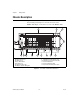
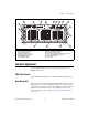
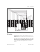
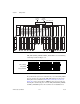
Figures 1-1 and 1-2 show the key features of the NI PXIe-1065 chassis
front and back panels. Figure 1-1 shows the front view of the
NI PXIe-1065. Figure 1-2 shows the rear view of the NI PXIe-1065.
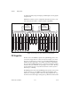
Figure 1-1. Front View of the NI PXIe-1065 Chassis
1 Chassis Carry Handle
2 Backplane Connectors
3 PXI Filler Panels
4 Chassis Model Name
5 Removable Feet
6 PXI Peripheral Slots (9x)
7 PXI Express System Timing Slot
8 PXI Express Hybrid Peripheral Slots (4x)
9 PXI Express Peripheral Slots (3x)
10 PXI Express System Controller Slot
11 Power Inhibit Switch
12 Power Inhibit Switch LED
13 System Controller Expansion Slots
181716151312111098765432
NI PXIe-1065
4
8
3
11
1
H
14
HHH
65 689
7810
2
1
13
5
12