PXI Express NI PXIe-1065 User Manual NI PXIe-1065 User Manual December 2008 371990B-01 TM
Support Worldwide Technical Support and Product Information ni.
Important Information Warranty The NI PXIe-1065 is warranted against defects in materials and workmanship for a period of one year from the date of shipment, as evidenced by receipts or other documentation. National Instruments will, at its option, repair or replace equipment that proves to be defective during the warranty period. This warranty includes parts and labor.
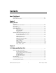
Contents About This Manual Conventions ...................................................................................................................vii Related Documentation..................................................................................................viii Chapter 1 Getting Started Unpacking ......................................................................................................................1-1 What You Need to Get Started ..........................................
Contents Installing a PXI Express System Controller.................................................................. 2-6 Installing Peripheral Modules........................................................................................ 2-8 Power Inhibit Switch LED Indicator............................................................................. 2-10 Remote Voltage Monitoring and Control...................................................................... 2-10 Inhibit Mode Switch .................
About This Manual The NI PXIe-1065 User Manual describes the features of the NI PXIe-1065 chassis and contains information about configuring the chassis, installing the modules, and operating the chassis. Conventions The following conventions are used in this manual: » The » symbol leads you through nested menu items and dialog box options to a final action. The sequence File»Page Setup»Options directs you to pull down the File menu, select the Page Setup item, and select Options from the last dialog box.
About This Manual Related Documentation The following documents contain information that you might find helpful as you read this manual: NI PXIe-1065 User Manual • IEEE 1101.1-1991, IEEE Standard for Mechanical Core Specifications for Microcomputers Using IEC 603-2 Connectors • IEEE 1101.10, IEEE Standard for Additional Mechanical Specifications for Microcomputers Using IEEE 1101.1 Equipment Practice • PICMG EXP.0 R1.
1 Getting Started This chapter describes the key features of the NI PXIe-1065 chassis and lists the kit contents and optional equipment you can order from National Instruments. Unpacking Carefully inspect the shipping container and the chassis for damage. Check for visible damage to the metal work. Check to make sure all handles, hardware, and switches are undamaged. Inspect the inner chassis for any possible damage, debris, or detached components.
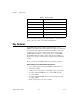
Chapter 1 Getting Started Table 1-1. AC Power Cables Power Cable Reference Standards Standard 120 V (USA) ANSI C73.11/NEMA 5-15-P/IEC83 Switzerland 220 V SEV Australia 240 V AS C112 Universal Euro 230 V CEE (7), II, IV, VII IEC83 North America 120 V ANSI C73.20/NEMA 5-15-P/IEC83 United Kingdom 230 V BS 1363/IEC83 If you are missing any of the items listed in Table 1-1, or if you have the incorrect AC power cable, contact National Instruments.
Chapter 1 Getting Started • Variable speed fan controller optimizes cooling and acoustic emissions • Remote power-inhibit control • Complies with PXI and CompactPCI Specifications High Reliability • 0 to 55 °C extended temperature range • Power supply, temperature, and fan monitoring • HALT tested for increased reliability • Field replaceable power supply shuttle Multi-Chassis Support • PXIe System Timing Slot for tight synchronization across chassis • Rear CLK10 I/O connectors • Switch
Chapter 1 Getting Started Chassis Description Figures 1-1 and 1-2 show the key features of the NI PXIe-1065 chassis front and back panels. Figure 1-1 shows the front view of the NI PXIe-1065. Figure 1-2 shows the rear view of the NI PXIe-1065.
Chapter 1 4 3 6 4 5 7 8 9 Getting Started 10 2 11 1 12 4 1 2 3 4 5 6 7 Universal AC Input Push-Reset Circuit Breaker Chassis Ground Screw Fan Guard Retainer Screws Power Supply Shuttle ID Label 10 MHz REF OUT BNC 10 MHz REF IN BNC 4 8 9 10 11 12 13 14 13 14 Remote Inhibit and Voltage Monitoring Connector Inhibit Mode Selector Switch Fan Speed Selector Switch Power Supply Shuttle Mounting Screws (10x) Power Supply Shuttle Handle (2x) Power Supply Shuttle Fan Guard Figure 1-2.
Chapter 1 Getting Started Slot Blockers Optional slot blocker kits are available from National Instruments for improved thermal performance when all slots are not used. NI PXIe-1065 Chassis Backplane Overview This section provides an overview of the backplane features for the NI PXIe-1065 chassis.
Chapter 1 Getting Started By default, the system controller will control the power supply with the PS_ON# signals. A logic low on this line will turn the power supply on. Note The Inhibit Mode switch on the rear of the chassis must be in the Default position for the system controller to have control of the power supply. Refer to the Inhibit Mode Switch section of Chapter 2, Installation and Configuration, for details about the Inhibit Mode switch.
Chapter 1 Getting Started PXI Express Peripheral Slots There are three PXI Express peripheral slots: slots 8–10. Slot 8 is directly connected to the system slot with a x4 PCI Express link. Slots 9 and 10 are connected to the system slot through a PCI Express switch. PXI Express peripheral slots can accept the following modules: • A PXI Express Peripheral with x4 or x1 PCI Express link to the system slot or through a switch to the system slot.
Chapter 1 Getting Started PXI STAR 16 PXI STAR 14 PXI STAR 15 PXI STAR 12 PXI STAR 13 PX DSTAR 10 PX STAR 11 PXI STAR 8 PXI STAR 4 PXI STAR 2 PXI STAR 9 PXI STAR 0 PXI STAR 7 PXI STAR 1 PXI STAR 6 H 13 H P2 P2 P2 P1 12 P1 H P1 11 P1 H PXIe_DSTAR 11 XP3 XP4 PXIe_DSTAR 8 P2 XP4 XP3 PXIe_DSTAR 1 XP4 XP3 TP2 7 PXI STAR 5 TP1 6 P1 5 P1 4 P1 XP3 3 XP4 XP4 XP3 2 XP3 XP4 XP3 1 XP4 XP4 P1 XP3 P1 P2 P2 P1 P2 P1 P2 10 P1 P2 9 P1 8 XP1 XP2 XP3 XP4 PXI STAR 3 14
Chapter 1 Getting Started Local bus signals may range from high-speed TTL signals to analog signals as high as 42 V. Initialization software uses the configuration information specific to each adjacent peripheral module to evaluate local bus compatibility.
Chapter 1 Getting Started assignments) can be configured through Measurement & Automation Explorer (MAX). Dynamic routing of triggers (automatic line assignments) is supported through certain National Instruments drivers like NI-DAQmx. Although any trigger line may be routed in either direction, it cannot be routed in more than one direction at a time.
Chapter 1 Getting Started 10 MHz REF IN 10 MHz REF OUT PXI_CLK10_IN P2 P2 P2 P2 XP4 XP3 XP3 H 13 H P1 12 P1 H P1 11 P1 H XP4 XP4 XP3 TP2 7 TP1 6 P1 5 P1 4 P1 XP3 3 XP4 XP4 XP3 2 XP3 XP4 XP3 1 XP4 XP4 XP3 P1 P2 P1 P2 P1 P2 P1 P2 10 P1 P2 9 P1 8 XP1 XP2 XP3 XP4 PXIe_CLK100 PXIe_SYNC100 PXI_CLK10 14 15 16 17 18 Figure 1-5.
Chapter 1 Getting Started signals to the slots (refer to Figure 1-5 for the distribution of PXI_CLK10, PXIe_CLK100 and PXIe_SYNC100). Refer to Appendix A, Specifications, for the specification information for an external clock provided on the PXI_CLK10_IN pin of the system timing slot. You also can drive a 10MHz clock on the 10 MHz REF IN connector on the rear of the chassis.
Chapter 1 Getting Started PXIe_SYNC_CTRL PXIe_SYNC100 is by default a 10 ns pulse synchronous to PXI_CLK10. The frequency of PXIe_SYNC100 is 10/n MHz, where n is a positive integer. The default for n is 1, giving PXIe_SYNC100 a 100 ns period. However, the backplane allows n to be programmed to other integers. For instance, setting n = 3 gives a PXIe_SYNC100 with a 300ns period while still maintaining its phase relationship to PXI_CLK10. The value for n may be set to any positive integer from 1 to 255.
Installation and Configuration 2 This chapter describes how to prepare and operate the NI PXIe-1065 chassis. Before connecting the chassis to a power source, read this chapter and the Read Me First: Safety and Radio-Frequency Interference document included with your kit. Safety Information Before undertaking any troubleshooting, maintenance, or exploratory procedure, carefully read the following caution notices.
Chapter 2 Installation and Configuration • Part Replacement—Only service this equipment with parts that are exact replacements, both electrically and mechanically. Contact National Instruments for replacement part information. Installation of parts with those that are not direct replacements may cause harm to personnel operating the chassis. Furthermore, damage or fire may occur if replacement parts are unsuitable. • Modification—Do not modify any part of the chassis from its original condition.
Chapter 2 Dimensions are in inches (millimeters) Installation and Configuration 1.75 (44.45) 1.75 (44.45) NI PXIe-1065 1 2 3 4 5 6 7 H 8 9 10 11 H 12 H 13 H 14 15 16 17 18 3.00 (76.20) Figure 2-1.
Chapter 2 Installation and Configuration 2 1 3 1 2 Primary Air Exhaust Vent Primary Air Intake Vent 3 Secondary Air Intake/Exhaust Vents (both sides) Figure 2-2. NI PXIe-1065 Vents Chassis Ambient Temperature Definition The chassis fan control system uses intake air temperature as the input for controlling fan speeds when in Auto Fan Speed mode. Because of this, the chassis ambient temperature is defined as the temperature that exists just outside of the fan intake vents on the rear of the chassis.
Chapter 2 Installation and Configuration rated ambient temperature as stated in Appendix A, Specifications. If the temperature exceeds the stated spec the power switch LED will blink green, as discussed in the Power Inhibit Switch LED Indicator section of this chapter. Setting Fan Speed The fan-speed selector switch is on the rear panel of the NI PXIe-1065 chassis. Refer to Figure 1-2, Rear View of the NI PXIe-1065 Chassis, to locate the fan-speed selector switch.
Chapter 2 Installation and Configuration If your power outlet does not have an appropriate ground connection, you must connect the premise safety ground to the chassis grounding screw located on the rear panel. Refer to Figure 1-2, Rear View of the NI PXIe-1065 Chassis, to locate the chassis grounding screw. To connect the safety ground, complete the following steps: 1. Connect a 16 AWG (1.3 mm) wire to the chassis grounding screw using a grounding lug.
Chapter 2 Installation and Configuration system controller to the rear of the chassis, making sure that the injector/ejector handle is pushed down as shown in Figure 2-3. 4 1 3 2 1 2 NI PXI Express System Controller NI PXIe-1065 Chassis 3 4 Injector/Ejector Handle System Controller Front Panel Mounting Screws (4x) Figure 2-3. Installing a PXIe System Controller 3. When you begin to feel resistance, pull up on the injector/ejector handle to seat the system controller fully into the chassis frame.
Chapter 2 Installation and Configuration Figure 2-4 shows a PXI Express system controller installed in the system controller slot of a NI PXIe-1065 chassis. You can place CompactPCI, CompactPCI Express, PXI, or PXI Express modules in other slots depending on the slot type. 1 2 3 1 NI PXIe-1065 Chassis 2 NI PXIe System Controller 3 Injector/Ejector Rail Figure 2-4.
Chapter 2 Installation and Configuration This section contains general installation instructions for installing a peripheral module in a NI PXIe-1065 chassis. Refer to your peripheral module user manual for specific instructions and warnings. To install a module, complete the following steps: 1. Connect the AC power source to the PXI Express chassis before installing the module. The AC power cord grounds the chassis and protects it from electrical damage while you install the module. 2.
Chapter 2 Installation and Configuration Power Inhibit Switch LED Indicator The chassis power inhibit switch has an integrated LED. This LED indicates one of four different conditions: • If the inhibit switch LED is steady green (not flashing), the chassis is powered on and operating normally. • If the inhibit switch LED is flashing green, the air-intake temperature has exceeded the chassis operating range.
Chapter 2 Installation and Configuration Table 2-1. Remote Inhibit and Voltage Monitoring Connector Pinout (Continued) DB-9 Pin Signal 8 –12 VDC 9 Logic Ground 6 1 7 2 8 3 9 4 5 Caution When connecting digital voltmeter probes to the rear 9-pin D-SUB (DB-9) connector, be careful not to short the probe leads together. Doing so could damage the power supply. You can use a digital voltmeter to ensure all voltage levels in the NI PXIe-1065 chassis are within the allowable limits.
Chapter 2 Installation and Configuration Inhibit Mode Switch On the rear panel of the chassis there is an Inhibit Mode switch. Refer to Figure 1-2, Rear View of the NI PXIe-1065 Chassis, for the location. The Inhibit Mode switch is recessed to prevent it from accidentally being switched. The Inhibit Mode switch should be in the Default position when normal power inhibit switch functionality is desired.
Chapter 2 Installation and Configuration double-driving and potentially damaging trigger lines. For more information about routing and reserving PXI triggers, refer to KnowledgeBase 3TJDOND8 at ni.com/support. The configuration steps for single or multiple-chassis systems are the same. Figure 2-6. Multichassis Configuration in MAX PXI-1 System Configuration 1. Launch MAX. 2. In the Configuration tree, click the Devices and Interfaces branch to expand it. 3.
Chapter 2 Installation and Configuration 4. Click the PXI system controller. The chassis (or multiple chassis, in a multichassis configuration) is listed below it. Identify each chassis by right-clicking its entry, then selecting the appropriate chassis model through the Identify As submenu. Further expanding the PXI System branch shows all devices in the system that can be recognized by NI-VISA. When your system controller and all your chassis are identified, the required pxisys.ini file is complete.
Chapter 2 Installation and Configuration Complete the following steps to reserve these trigger lines in MAX. 1. In the Configuration tree, click on the PXI chassis branch you want to configure. 2. Then, in the right-hand pane, toward the bottom, click on the Triggers tab. 3. Select which trigger lines you would like to statically reserve. 4. Click the Apply button.
Chapter 2 Installation and Configuration Using System Configuration and Initialization Files The PXI Express specification allows many combinations of PXI Express chassis and system modules. To assist system integrators, the manufacturers of PXI Express chassis and system modules must document the capabilities of their products. The minimum documentation requirements are contained in .ini files, which consist of ASCII text. System integrators, configuration utilities, and device drivers can use these .
3 Maintenance This chapter describes basic maintenance procedures you can perform on the NI PXIe-1065 chassis. Caution Disconnect the power cable prior to servicing a NI PXIe-1065 chassis. Service Interval Clean dust from the chassis exterior (and interior) as needed, based on the operating environment. Periodic cleaning increases reliability. Preparation The information in this section is designed for use by qualified service personnel.
Chapter 3 Maintenance Exterior Cleaning Clean the exterior surfaces of the chassis with a dry lint-free cloth or a soft-bristle brush. If any dirt remains, wipe with a cloth moistened in a mild soap solution. Remove any soap residue by wiping with a cloth moistened with clear water. Do not use abrasive compounds on any part of the chassis. Avoid getting moisture inside the chassis during exterior cleaning, especially through the top vents. Use just enough moisture to dampen the cloth.
Chapter 3 6. Maintenance The over-current condition that caused the circuit breaker to trip may be due to a faulty CompactPCI or PXI Express module. Refer to the documentation supplied with the modules for troubleshooting information. Replacing the Modular Power Supply This section describes how to remove, configure, and install the AC power supply shuttle in the NI PXIe-1065 chassis. Cautions Disconnect the power cable prior to replacing the power supply.
Chapter 3 Maintenance Configuration The fan-speed selector switch is on the rear panel of the power supply shuttle. Refer to Figure 1-2, Rear View of the NI PXIe-1065 Chassis, to locate the fan-speed selector. Select High for maximum cooling performance (recommended) or Auto for quieter operation. Set the Inhibit Mode switch to the Default position. Connecting Safety Ground Refer to the Connecting Safety Ground section of Chapter 2, Installation and Configuration.
A Specifications This appendix contains specifications for the NI PXIe-1065 chassis. Caution Specifications are subject to change without notice. Electrical AC Input Input voltage range................................. 100 to 240 VAC Operating voltage range1 ........................ 90 to 264 VAC Input frequency ...................................... 50/60 Hz Operating frequency range1 ................... 47 to 63 Hz Input current rating................................. 10–5 A Over-current protection...
Appendix A Specifications DC Output DC current capacity (IMP) Voltage Note Maximum Current +3.3 V 61 A +5 V 56 A +12 V 45 A –12 V 4A 5 VAUX 1.5 A Maximum combined +3.3 V, +5 V, and +12 V power is 699 W. Maximum total power is 701.5 W. The maximum power dissipated in the system slot should not exceed 140 W. Backplane pin current capacity Slot +5 V V (I/O) +3.
Appendix A Specifications Maximum ripple and noise (20 MHz bandwidth) Voltage Maximum Ripple and Noise +3.3 V 50 mVpp +12 V 120 mVpp +5 V 50 mVpp –12 V 120 mVpp Over-current protection.......................... All outputs protected from short circuit and overload with automatic recovery Over-voltage protection 3.3 V and 5 V .................................. Clamped at 20 to 30% above nominal output voltage Power supply shuttle MTTR ..................
Appendix A Specifications Environmental Maximum altitude...................................2,000 m (800 mbar) (at 25 °C ambient) Pollution Degree .....................................2 For indoor use only. Operating Environment Ambient temperature range ....................0 to 55 °C (Tested in accordance with IEC-60068-2-1 and IEC-60068-2-2. Meets MIL-PRF-28800F Class 3 low temperature limit and MIL-PRF-28800F Class 2 high temperature limit.) Relative humidity range..........................
Appendix A Specifications Acoustic Emissions Sound Pressure Level (at Operator Position) (Tested in accordance with ISO 7779. Meets MIL-PRF-28800F requirements.) Auto fan (up to ~30 °C ambient) ........... 45.0 dBA High fan.................................................. 63.3 dBA Sound Power Auto fan (up to ~30 °C ambient) ........... 55.5 dBA High fan.................................................. 76.2 dBA Note Specifications are subject to change without notice.
Appendix A Specifications Note For EMC compliance, operate this device with shielded cabling. CE Compliance This product meets the essential requirements of applicable European Directives as follows: • 2006/95/EC; Low-Voltage Directive (safety) • 2004/108/EC; Electromagnetic Compatibility Directive (EMC) Online Product Certification Refer to the product Declaration of Conformity (DoC) for additional regulatory compliance information.
Appendix A Specifications Backplane Size......................................................... 3U-sized; one system slot (with three system expansion slots) and 17 peripheral slots. Compliant with IEEE 1101.10 mechanical packaging. PXI Express Specification compliant. Accepts both PXI Express and CompactPCI (PICMG 2.0 R 3.0) 3U modules. Backplane bare-board material .............. UL 94 V-0 Recognized Backplane connectors ............................
Appendix A Specifications Maximum jitter .......................................3 ps RMS phase-jitter (10 Hz–12 kHz range) 2 ps RMS phase-jitter (12 kHz–20 MHz range) Duty-factor for PXIe_CLK100...............45%–55% Absolute single-ended voltage swing (When each line in the differential pair has 50 W termination to 1.30 V or Thévenin equivalent)..........................400–1000 mV Note For other specifications refer to the PXI-5 PXI Express Hardware Specification.
Appendix A Specifications PXIe_SYNC_CTRL VIH .......................................................... 2.0–5.5 V VIL .......................................................... 0–0.8 V PXI Star Trigger Maximum slot-to-slot skew ................... 250 ps Backplane characteristic impedance ...... 65 Ω ±10% For PXI slot to PXI Star mapping refer to the System Timing Slot section of Chapter 1, Getting Started. Note For other specifications refer to the PXI-1 Hardware Specification.
Appendix A Specifications Weight ....................................................12.8 kg (28.2 lb) Chassis materials ....................................Sheet Aluminum (5052-H32, 3003-H14, and 6061-T6), Extruded Aluminum (6060-T6), and Cold Rolled Steel, PC-ABS, Santoprene, Nylon Finish ......................................................Conductive Clear Iridite on Aluminum Electroplated Nickel on Cold Rolled Steel Polyurethane Enamel NI PXIe-1065 User Manual A-10 ni.
Appendix A Specifications Figures A-1 and A-2 show the NI PXIe-1065 chassis dimensions. The holes shown are for the installation of the optional rack mount kits. You can install those kits on the front or rear of the chassis, depending on which end of the chassis you want to face toward the front of the instrument cabinet. Notice that the front and rear chassis mounting holes (size M4) are symmetrical. Dimensions are in inches (millimeters) .39 (9.9) 17.54 (445.6) NI PXIe-1065 6.97 (177.
Appendix A Specifications Dimensions are in inches (millimeters) 12.700 (322.58) 2.524 (64.11) 15.504 (393.8) 1.017 (25.83) Figure A-2. NI PXIe-1065 Chassis Dimensions (Bottom) NI PXIe-1065 User Manual A-12 ni.
Appendix A Specifications Figure A-3 shows the chassis rack mount kit components. 2 NI PX Ie- 10 65 3 1 1 Front Rack Mount Kit 2 NI Chassis 3 Optional Rear Rack Mount Kit Figure A-3. NI Chassis Rack Mount Kit Components The chassis shown in Figure A-3 is representative of the NI PXI-1044/1045 and NI PXIe-1065 product line.
B Pinouts This appendix describes the connector pinouts for the NI PXIe-1065 chassis backplane. Table B-1 shows the XP1 connector pinout for the System Controller slot. Table B-2 shows the XP2 Connector Pinout for the System Controller slot. Table B-3 shows the XP3 Connector Pinout for the System Controller slot. Table B-4 shows the XP4 Connector Pinout for the System Controller slot. Table B-5 shows the TP1 Connector Pinout for the System Controller slot.
Appendix B Pinouts System Controller Slot Pinouts Table B-1. XP1 Connector Pinout for the System Controller Slot Pins Signals A GND B 12V C 12V D GND E 5V F 3.3V G GND Table B-2.
Appendix B Pinouts Table B-3. XP3 Connector Pinout for the System Controller Slot (Continued) Pin A B ab C D cd E F ef 7 1PETp3 1PETn3 GND 1PERp3 1PERn3 GND 2PETp0 2PETn0 GND 8 2PETp1 2PETn1 GND 2PERp1 2PERn1 GND 2PERp0 2PERn0 GND 9 2PETp2 2PETn2 GND 2PERp2 2PERn2 GND 2PETp3 2PETn3 GND 10 3PETp0 3PETn0 GND 3PERp0 3PERn0 GND 2PERp3 2PERn3 GND Table B-4.
Appendix B Pinouts Table B-6.
Appendix B Pinouts Peripheral Slot Pinouts Table B-9. P1 Connector Pinout for the Peripheral Slot Pin Z A B C D E F 25 GND 5V REQ64# ENUM# 3.3V 5V GND 24 GND AD[1] 5V V(I/O) AD[0] ACK64# GND 23 GND 3.3V AD[4] AD[3] 5V AD[2] GND 22 GND AD[7] GND 3.3V AD[6] AD[5] GND 21 GND 3.3V AD[9] AD[8] M66EN C/BE[0]# GND 20 GND AD[12] GND V(I/O) AD[11] AD[10] GND 19 GND 3.3V AD[15] AD[14] GND AD[13] GND 18 GND SERR# GND 3.
Appendix B Pinouts Table B-10.
Appendix B Pinouts Hybrid Slot Pinouts Table B-11. P1 Connector Pinout for the Hybrid Slot Pin Z A B C D E F 25 GND 5V REQ64# ENUM# 3.3V 5V GND 24 GND AD[1] 5V V(I/O) AD[0] ACK64# GND 23 GND 3.3V AD[4] AD[3] 5V AD[2] GND 22 GND AD[7] GND 3.3V AD[6] AD[5] GND 21 GND 3.3V AD[9] AD[8] M66EN C/BE[0]# GND 20 GND AD[12] GND V(I/O) AD[11] AD[10] GND 19 GND 3.3V AD[15] AD[14] GND AD[13] GND 18 GND SERR# GND 3.3V PAR C/BE[1]# GND 17 GND 3.
Appendix B Pinouts Table B-12.
Technical Support and Professional Services C Visit the following sections of the award-winning National Instruments Web site at ni.com for technical support and professional services: • Support—Technical support at ni.com/support includes the following resources: – Self-Help Technical Resources—For answers and solutions, visit ni.
Appendix C Technical Support and Professional Services • Declaration of Conformity (DoC)—A DoC is our claim of compliance with the Council of the European Communities using the manufacturer’s declaration of conformity. This system affords the user protection for electromagnetic compatibility (EMC) and product safety. You can obtain the DoC for your product by visiting ni.com/certification. If you searched ni.
Glossary Symbol Prefix Value p pico 10 –12 n nano 10 –9 μ micro 10 – 6 m milli 10 –3 k kilo 10 3 M mega 10 6 G giga 10 9 T tera 10 12 Symbols ° Degrees. ≥ Equal or greater than. ≤ Equal or less than. % Percent. A A Amperes. AC Alternating current. ANSI American National Standards Institute. Auto Automatic fan speed control. AWG American Wire Gauge.
Glossary B backplane An assembly, typically a printed circuit board, with connectors and signal paths that bus the connector pins. BNC Bayonet Neill Concelman connector; a commonly used coaxial connector. C C Celsius. cfm Cubic feet per minute. CFR Code of Federal Regulations. cm Centimeters. CompactPCI An adaptation of the Peripheral Component Interconnect (PCI) Specification 2.
Glossary E efficiency Ratio of output power to input power, expressed as a percentage. EIA Electronic Industries Association. EMC Electromagnetic Compatibility. EMI Electromagnetic Interference. F FCC Federal Communications Commission. filler panel A blank module front panel used to fill empty slots in the chassis. G g (1) grams; (2) a measure of acceleration equal to 9.8 m/s2. GPIB General Purpose Interface Bus (IEEE 488). gRMS A measure of random vibration.
Glossary in. Inches. inhibit To turn off. J jitter A measure of the small, rapid variations in clock transition times from their nominal regular intervals. Units: seconds RMS. K kg Kilograms. km Kilometers. L lb Pounds. LED Light emitting diode. line regulation The maximum steady-state percentage that a DC voltage output will change as a result of a specified change in input AC voltage (step change from 90 to 132 VAC or 180 to 264 VAC).
Glossary N NEMA National Electrical Manufacturers Association. NI National Instruments. P power supply shuttle A removable module that contains the chassis power supply. PXI PCI eXtensions for Instrumentation. PXI_CLK10 10 MHz PXI system reference clock. R RH Relative humidity. RMS Root mean square. S s Seconds. skew Deviation in signal transmission times. slot blocker An assembly installed into an empty slot to improve the airflow in adjacent slots.
Glossary system reference clock A 10 MHz clock, also called PXI_CLK10, that is distributed to all peripheral slots in the chassis, as well as a BNC connector on the rear of chassis labeled 10 MHz REF OUT. The system reference clock can be used for synchronization of multiple modules in a measurement or control system. The 10 MHz REF IN and OUT BNC connectors on the rear of the chassis can be used to synchronize multiple chassis to one reference clock.
Index A CompactPCI interoperability with NI PXIe-1065 backplane, 1-6 configuration in MAX (figure), 2-13 configuration. See installation, configuration, and operation connector pinouts.
Index F setting fan speed, 2-5 site considerations, 2-2 slot blocker installation, 2-5 testing power up, 2-6 unpacking the PXIe-1065, 1-1 installing a PXI Express system controller (figure), 2-7 instrument drivers (NI resources), C-1 interoperability with CompactPCI, 1-6 fan, setting speed, 2-5 filler panel installation, 2-5 G ground, connecting, 2-5 H help, technical support, C-1 hybrid peripheral slots, description, 1-7 hybrid slot pinouts P1 connector (table), B-7 XP3 connector (table), B-8 XP4 conn
Index power supply connecting to, 2-6 remote voltage monitoring and inhibiting interface, 2-10 replacing, 3-3 configuration, 3-4 connecting safety ground, 3-4 connecting to power source, 3-4 installation, 3-3 removal, 3-3 voltages at voltage monitoring connector (DB-9) (table), 2-10 power up, testing, 2-6 programming examples (NI resources), C-1 PXI differential star trigger specifications (PXIe-DSTARA, PXIe-DSTARB, PXIe-DSTARC), A-9 PXI Express configuration in MAX, 2-12 PXI Express peripheral slots, desc
Index mechanical, A-9 online product certification, A-6 PXI differential star triggers (PXIe-DSTARA, PXIe-DSTARB, PXIe-DSTARC), A-9 PXI star trigger, A-9 PXIe_SYNC_CTRL, A-9 rack mount kit dimensions (figure), A-13 safety, A-5 shock and vibration, A-4 system reference clocks, A-7 static discharge damage (caution), 3-1 support, technical, C-1 system controller slot description, 1-6 pinouts XP1 connector (table), B-2 XP2 connector (table), B-2 XP3 connector (table), B-2 XP4 connector (table), B-3 system refe
Index U W unpacking the NI PXIe-1065 chassis, 1-1 Web resources, C-1 WEEE information, A-6 V voltage monitoring connector.