
Network Card User Manual
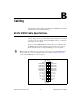
Table Of Contents
- IMAQ PCI/PXI-1428 User Manual
- Support
- Important Information
- Compliance
- Conventions
- Contents
- Chapter 1 Introduction
- Chapter 2 Installation
- Chapter 3 Hardware Overview
- Functional Overview
- Figure 3-1. IMAQ 1428 Block Diagram
- Camera Link and IMAQ 1428
- Data Transmission
- LUTs
- Multiple-Tap Data Formatter
- SDRAM
- Trigger Control and Mapping Circuitry
- High-Speed Timing
- Acquisition and Region of Interest (ROI)
- Scatter-Gather DMA Controllers
- Bus Master PCI Interface
- Start Conditions
- Acquisition Window Control
- Serial Interface
- Functional Overview
- Chapter 4 Signal Connections
- Appendix A Specifications
- Appendix B Cabling
- Appendix C Technical Support and Professional Services
- Glossary
- Index

Appendix A Specifications
IMAQ PCI/PXI-1428 User Manual A-2 ni.com
Clocks
Pixel clock frequency range....................20 to 50 MHz
Note Camera Link cameras must transmit at a minimum of 20 MHz.
1
PCI Interface
Theoretical max PCI bandwidth .............133 MB/s
Memory
Onboard memory
PCI-1428..........................................16 MB SDRAM
PXI-1428 .........................................32 MB SDRAM
LUTs.......................................................Four 8-bit; two 10-bit to 16-bit
Serial Requirements
Baud rates supported ..............................300, 600, 1200, 1800, 2000, 2400,
3600, 4800, 7200, or 9600 bps;
19.2, 38.4, or 56 kbps
Power Requirements
Voltage
PCI-1428..........................................+5 V (1.5 A)
+12 V (24 mA)
–12 V (20 mA)
PXI-1428 .........................................+5 V (250 mA)
+3.3 V (1.2 A)
Physical
Dimensions
PCI-1428..........................................10.7 cm × 17.5 cm
(4.2 in. × 6.9 in.)
PXI-1428 .........................................10 cm × 16 cm
(3.9 in. × 6.3 in.)
1
This value corresponds to the post-serialization Camera Link cable transmission rate of 140 to 350 MHz.