
Network Card User Manual
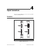
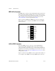
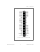
Table Of Contents
- IMAQ PCI/PXI-1428 User Manual
- Support
- Important Information
- Compliance
- Conventions
- Contents
- Chapter 1 Introduction
- Chapter 2 Installation
- Chapter 3 Hardware Overview
- Functional Overview
- Figure 3-1. IMAQ 1428 Block Diagram
- Camera Link and IMAQ 1428
- Data Transmission
- LUTs
- Multiple-Tap Data Formatter
- SDRAM
- Trigger Control and Mapping Circuitry
- High-Speed Timing
- Acquisition and Region of Interest (ROI)
- Scatter-Gather DMA Controllers
- Bus Master PCI Interface
- Start Conditions
- Acquisition Window Control
- Serial Interface
- Functional Overview
- Chapter 4 Signal Connections
- Appendix A Specifications
- Appendix B Cabling
- Appendix C Technical Support and Professional Services
- Glossary
- Index

© National Instruments Corporation A-1 IMAQ PCI/PXI-1428 User Manual
A
Specifications
This appendix lists the specifications of the IMAQ 1428. These
specifications are typical at 25 °C, unless otherwise stated.
External Connections
Number of external trigger I/O lines...... 4
Trigger input
Voltage range.................................. 0 to 5 V (TTL)
Input high voltage.................... 2.0 V
Input low voltage ..................... 0.8 V
Polarity............................................ Programmable,
active-high or active-low
Trigger output
Voltage range.................................. 0 to 5 V (TTL)
Output high voltage ................. 2.4 V at 15 mA source
Output low voltage .................. 0.55 V at 10 mA sink
Polarity............................................ Programmable,
active-high or active-low
Power-on state........................................ Input (high-impedance)
10 KΩ pull-up to 5 V
Pixel clock.............................................. Camera Link compatible
Enables ................................................... Camera Link compatible
Control signal......................................... Camera Link compatible
Video data .............................................. Camera Link compatible