
Network Card User Manual
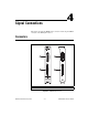
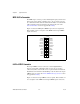
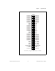
Table Of Contents
- IMAQ PCI/PXI-1428 User Manual
- Support
- Important Information
- Compliance
- Conventions
- Contents
- Chapter 1 Introduction
- Chapter 2 Installation
- Chapter 3 Hardware Overview
- Functional Overview
- Figure 3-1. IMAQ 1428 Block Diagram
- Camera Link and IMAQ 1428
- Data Transmission
- LUTs
- Multiple-Tap Data Formatter
- SDRAM
- Trigger Control and Mapping Circuitry
- High-Speed Timing
- Acquisition and Region of Interest (ROI)
- Scatter-Gather DMA Controllers
- Bus Master PCI Interface
- Start Conditions
- Acquisition Window Control
- Serial Interface
- Functional Overview
- Chapter 4 Signal Connections
- Appendix A Specifications
- Appendix B Cabling
- Appendix C Technical Support and Professional Services
- Glossary
- Index
© National Instruments Corporation 4-1 IMAQ PCI/PXI-1428 User Manual
4
Signal Connections
This chapter describes the MDR 26-pin connector and the 68-pin VHDCI
connector on the IMAQ 1428 device.
Connectors
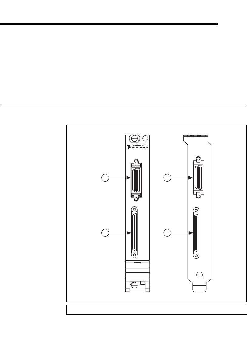
Figure 4-1 shows the connectors on the IMAQ 1428 device.
Figure 4-1. IMAQ 1428 Connectors
1 MDR 26-Pin Connector 2 68-Pin VHDCI Connector
TRIGGERS
CAMERA LINK
NI PXI-1428
Image Acquisition
TRIGGERS
CAMERA LINK
2
1
2
1