
Portable Monitor Accessory User Guide and Specifications Sheet

© National Instruments Corporation 5 NI PMA-1115 User Guide and Specifications
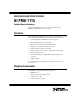
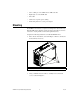
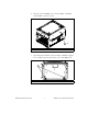
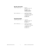
6. Orient the chassis and PMA-1115 as shown in Figure 5. Install the
remaining M4 × 8 pan-head screws.
Figure 5. Installing the PMA-1115
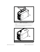
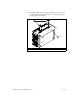
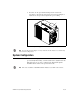
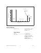
7. Open the keyboard and LCD, as shown in Figure 6. Install the supplied
6-32 × 3/8 flat-head screws in the lower corners of the PMA-1115.
Figure 6. Installing the Lower Mounting Screws
1M4× 8 pan-head screws
16-32× 3/8 flat-head screws
1
(4x)
1