LabWindows /CVI TM PID Control Toolkit User Manual LabWindows/CVI PID Control Toolkit User Manual May 2008 371685C-01 TM
Support Worldwide Technical Support and Product Information ni.
Important Information Warranty The media on which you receive National Instruments software are warranted not to fail to execute programming instructions, due to defects in materials and workmanship, for a period of 90 days from date of shipment, as evidenced by receipts or other documentation. National Instruments will, at its option, repair or replace software media that do not execute programming instructions if National Instruments receives notice of such defects during the warranty period.
Contents About This Manual Conventions ...................................................................................................................vii Related Documentation..................................................................................................vii Chapter 1 Overview of the PID Control Toolkit System Requirements ....................................................................................................1-1 Installation Instructions...................................
Contents Converting between Percentage of Full Scale and Engineering Units ........... 3-9 Using PID on Real-Time (RT) Targets........................................................... 3-10 Using PID with DAQ Devices ........................................................................ 3-10 Appendix A References Appendix B Technical Support and Professional Services Glossary Index LabWindows/CVI PID Control Toolkit User Manual vi ni.
About This Manual The LabWindows/CVI PID Control Toolkit User Manual describes the PID Control Toolkit for LabWindows™/CVI™. The manual describes the features, functions, and operation of the toolkit. To use this manual, you need a basic understanding of process control strategies and algorithms. Conventions The following conventions appear in this manual: » The » symbol leads you through nested menu items and dialog box options to a final action.
Overview of the PID Control Toolkit 1 This chapter describes how to install the toolkit and describes Proportional-Integral-Derivative (PID) control applications. System Requirements Your computer must meet the following minimum system requirements to run the PID Control Toolkit: • LabWindows/CVI 7.
Chapter 1 Overview of the PID Control Toolkit Activation Instructions The first time you launch LabWindows/CVI after installing the PID Control Toolkit, you are prompted to activate the toolkit. Complete the following steps to activate the PID Control Toolkit. 1. Click Activate Products. 2. Select the Automatically activate through a secure Internet connection option and click Next. Your computer must be connected to the Internet for this option to work.
Chapter 1 Overview of the PID Control Toolkit PID Control Currently, the PID algorithm is the most common control algorithm used in industry. Often, PID is used to control processes that include heating and cooling systems, fluid level monitoring, flow control, and pressure control. When using PID control, you must specify a process variable and a setpoint. The process variable is the system parameter you want to control, such as temperature, pressure, or flow rate.
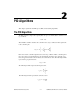
2 PID Algorithms This chapter explains the fast PID, precise PID, and autotuning algorithms. The PID Algorithm The PID controller compares the setpoint (SP) to the process variable (PV) to obtain the error (e), as follows: e = SP – PV Then the PID controller calculates the controller action, u(t), as follows. In this equation, Kc is the controller gain.
Chapter 2 PID Algorithms Implementing the PID Algorithm with the PID Functions This section describes how the PID Control Toolkit functions implement the fast (positional) PID algorithm. The fast PID algorithm is the default algorithm used in the PID Control Toolkit. Error Calculation The following formula represents the current error used in calculating proportional, integral, and derivative action, where PVf is the filtered process variable.
Chapter 2 PID Algorithms Output Limiting The actual controller output is limited to the range specified for control output, as follows: if u ( k ) ≥ u max then u ( k ) = u max and if u ( k ) ≤ u min then u ( k ) = u min The following formula shows the practical model of the PID controller. t 1 u ( t ) = K c ( SP – PV ) + ---Ti ∫ 0 dPV f (SP – PV)dt – T d -----------dt The PID functions use an integral sum correction algorithm that facilitates anti-windup and bumpless manual-to-automatic transfers.
Chapter 2 PID Algorithms The Precise PID Algorithm This section describes how the PID Control Toolkit functions implement the precise PID algorithm.
Chapter 2 PID Algorithms Trapezoidal Integration Trapezoidal integration is used to avoid sharp changes in integral action when there is a sudden change in the PV or SP. The following formula represents the trapezoidal integration action for the precise PID algorithm. Use nonlinear adjustment of integral action to counteract the overshoot. The larger the error, the smaller the integral action, as shown in the following formula and in Figure 2-1.
Chapter 2 PID Algorithms Figure 2-2 illustrates the autotuning procedure excited by the setpoint relay experiment, which connects a relay and an extra feedback signal with the SP. Notice that the PID Library autotuning functions directly implement this process. The existing controller remains in the loop. SP + – + – PV e P(I) Controller Process Relay Figure 2-2.
Chapter 2 PID Algorithms Table 2-2. Tuning Formula under P-Only Control (Normal) Controller Kc Ti Td P 0.2Ku — — PI 0.18Ku 0.8Tu — PID 0.25Ku 0.5Tu 0.12Tu Table 2-3. Tuning Formula under P-Only Control (Slow) Controller Kc Ti Td P 0.13Ku — — PI 0.13Ku 0.8Tu — PID 0.15Ku 0.5Tu 0.12Tu Table 2-4. Tuning Formula under PI or PID Control (Fast) Controller Kc Ti Td — — P Tp /τ PI 0.9Tp /τ 3.33τ — PID 1.1Tp /τ 2.0τ 0.5τ Table 2-5.
Chapter 2 PID Algorithms Table 2-6. Tuning Formula under PI or PID Control (Slow) Controller Kc Ti Td P 0.26Tp /τ — — PI 0.24Tp /τ 5.33τ — PID 0.32Tp /τ 4.0τ 0.8τ During tuning, the process remains under closed-loop PID control. It is not necessary to switch off the existing controller and perform the experiment under open-loop conditions. In the setpoint relay experiment, the SP signal mirrors the SP for the PID controller. Note LabWindows/CVI PID Control Toolkit User Manual 2-8 ni.
Using the PID Control Toolkit 3 This chapter contains the basic information you need to design a control strategy using the PID Control Toolkit functions. Designing a Control Strategy When you design a control strategy, sketch a flowchart that includes the physical process and control elements such as valves and measurements. Add feedback from the process and any required computations. Then use the PID Control Toolkit functions to translate the flowchart into an application.
Chapter 3 Using the PID Control Toolkit Tuning Controllers Manually The following controller tuning procedures are based on the work of Ziegler and Nichols, the developers of the Quarter-Decay Ratio tuning techniques derived from a combination of theory and empirical observations (Corripio 1990). Experiment with these techniques and the process control simulation examples to compare them. For different processes, one method might be easier or more accurate than another.
Chapter 3 Using the PID Control Toolkit Open-Loop (Step Test) Tuning Procedure The open-loop (step test) tuning procedure assumes that you can model any process as a first-order lag and a pure deadtime. This method requires more analysis than the closed-loop tuning procedure, but the process does not need to reach sustained oscillation. Therefore, the open-loop tuning procedure might be quicker and more reliable for many processes.
Chapter 3 Using the PID Control Toolkit Using the PID Library The following sections describe how to use the PID Library to implement a control strategy. PID Controller The PID controller requires several inputs, including SP, PID gains, timer interval (in case the internal timer is not used), PV, and output range. PID gains include proportional gain, integral time, and derivative time. The following steps provide an overview of typical PID controller use. 1.
Chapter 3 Using the PID Control Toolkit The fast PID algorithm is faster and simpler than the precise PID algorithm. Use the fast algorithm in fast control loops. The precise PID algorithm uses the Two Degree of Freedom algorithm to control the PV, which gives better results than the fast PID algorithm. The precise PID algorithm also uses extra parameters such as Beta, Linearity, and Setpoint Range, which you can specify using PidSetAttribute.
Chapter 3 Using the PID Control Toolkit Using PID with Autotuning You can use autotuning to improve controller performance. There are two ways in which you can autotune a controller. • Wizard-Based Autotuning—You can use the PID Autotuning Wizard to tune the parameters. • Classic Autotuning—You can use the functions in the Autotuning class to develop a custom autotuning user interface. Complete the following steps to autotune a controller. These steps explain both wizard-based and classic autotuning.
Chapter 3 Using the PID Control Toolkit If you are using LabWindows/CVI 8.0 and later, click Add Additional Module in the Drivers & Components tab of the Edit Installer dialog box. In the Select Merge Module dialog box, browse to and select CVIPIDRuntime.msm. For additional information about distributing LabWindows/CVI applications, refer to the LabWindows/CVI Help. Using PID with Gain Scheduling Most processes are non-linear.
Chapter 3 Using the PID Control Toolkit Using PID with Lead-Lag The lead-lag compensator uses a positional algorithm that approximates a true exponential lead-lag. Feed forward control schemes often use this kind of algorithm as a dynamic compensator. Using lead-lag, you can simulate inertia of motors, slow settling times in pipes, and so on. Lead compensation stabilizes a closed loop by reacting to how fast something is changing rather than its current state. This process speeds up the reaction.
Chapter 3 Using the PID Control Toolkit You can use the setpoint profiler as follows: 1. Call PidSetpointProfileCreate to create a setpoint profile. Use a pair of time and setpoint value arrays to specify the setpoint profile with the time values in ascending order. 2. Use PidSetSetpointProfileAttribute to set the setpoint profile attributes. 3. Use PidSetpointProfileNextSetpoint to obtain the setpoint from the profile in a loop and provide this setpoint to the controller. 4.
Chapter 3 Using the PID Control Toolkit value of 1 produces an output of 10 for a difference between the SP and PV of 10, regardless of the output range and setpoint range. Using PID on Real-Time (RT) Targets Some PID applications are deterministic and, therefore, cannot be run on desktop operating systems. Because the PID Library is supported on real-time (RT) targets, you can use it to develop deterministic applications.
Chapter 3 Using the PID Control Toolkit The control loops can be timed in the following ways: • Software-Timed—In software-timed control loops, the timing is controlled by the software loop rate. You can implement a software loop with a timer construct, such as a timer control or asynchronous timer, or a while loop with a delay or sleep operation at the end. • Hardware-Timed—In hardware-timed control loops, the timing is controlled by the DAQ device.
A References The Instrument Society of America (ISA), the organization that sets standards for process control instrumentation in the United States, offers a catalog of books, journals, and training materials to teach you the basics of process control programming. The Corripio (1990) publication is an ISA Independent Learning Module book. It is organized as a self-study program covering measurement and control techniques, selection of controllers, and advanced control techniques.
Technical Support and Professional Services B Visit the following sections of the award-winning National Instruments Web site at ni.com for technical support and professional services: • Support—Technical support resources at ni.com/support include the following: – Self-Help Technical Resources—For answers and solutions, visit ni.
Appendix B Technical Support and Professional Services If you searched ni.com and could not find the answers you need, contact your local office or NI corporate headquarters. Phone numbers for our worldwide offices are listed at the front of this manual. You also can visit the Worldwide Offices section of ni.com/niglobal to access the branch office Web sites, which provide up-to-date contact information, support phone numbers, email addresses, and current events.
Glossary A algorithm A prescribed set of well-defined rules or processes for the solution of a problem in a finite number of steps. autotuning Automatically testing a process under control to determine the controller gains that will provide the best controller performance. Autotuning Wizard An automated graphical user interface provided in the Autotuning functions. The Autotuning Wizard gathers some information about the desired control from the user and then steps through the PID autotuning process.
Glossary D damping The progressive reduction or suppression of oscillation in a device or system. dead time (Td) The interval of time, expressed in minutes, between initiation of an input change or stimulus and the start of the resulting observable response. derivative (control) action Control response to the time rate of change of a variable. E EGU Engineering units.
Glossary I Instrument Society of America (ISA) The organization that sets standards for process control instrumentation in the United States. integral (control) action Control action in which the output is proportional to the time integral of the input. That is, the rate of change of output is proportional to the input. K K Process gain. Kc Controller gain. L lag A lowpass filter or integrating response with respect to time.
Glossary O output limiting Preventing a controller’s output from traveling beyond a desired maximum range. overshoot The maximum excursion beyond the final steady-state value of output as the result of an input change. P P Proportional. PD Proportional, derivative. PI Proportional, integral. PID Proportional, integral, derivative. PID control A common control strategy in which a process variable is measured and compared to a desired setpoint to determine an error signal.
Glossary R ramp The total (transient plus steady-state) time response resulting from a sudden increase in the rate of change from zero to some finite value of input stimulus. reentrant execution Mode in which calls to multiple instances of a function can execute in parallel with distinct and separate data storage. S s Seconds. setpoint (SP) An input variable that sets the desired value of the controlled process variable. span The algebraic difference between the upper and lower range values.
Index A D applications, 1-3 autotuning, 3-6 classic, 3-6 procedure, 3-6 wizard based, 3-6 distributing applications, 3-6 autotuning algorithm tuning formulas, 2-6 PI control (fast), 2-7 PI control (normal), 2-7 PI control (slow), 2-8 P-only control (normal), 2-7 P-only control (slow), 2-7 DAQ devices, using PID with, 3-10 derivative action, 2-1 derivative time, 2-1 diagnostic tools (NI resources), B-1 distributing applications, 3-6 documentation conventions used in manual, vii NI resources, B-1 related d
Index I nonlinear adjustment of integral action, 2-2 output limiting, 2-3 partial derivative action, 2-2 proportional action, 2-2 trapezoidal integration, 2-2 gain scheduling, 2-3 PID controller, 1-3 typical use, 3-4 PID Library, 3-4 pidAttrAlgorithm, 3-4 pidAttrLimitOutputRate, 3-5 pidAttrUseInternalTimer, 3-1 pidGSAttrGainScheduleCriteria, 3-7 precise PID algorithm, 2-4, 3-4 calculating controller action nonlinear adjustment of integral action, 2-5 proportional action, 2-4 trapezoidal integration, 2-5 e
Index S U setpoint, 1-3 relay experiment, 2-6 software (NI resources), B-1 step test tuning procedure, 3-3 support, technical, B-1 system requirements, 1-1 ultimate gain tuning procedure, 3-2 W Web resources, B-1 windup, 2-3 wizard-based autotuning, 3-6 distributing applications, 3-6 T technical support, B-1 timing information, acquiring, 3-1 timing, setting, 3-1 training and certification (NI resources), B-1 trapezoidal integration, 2-2, 2-5 troubleshooting (NI resources), B-1 tuning procedure closed