SCXI TM SCXI Chassis User Manual SCXI Chassis User Manual May 2004 Edition Part Number 320423H-01
Worldwide Technical Support and Product Information ni.
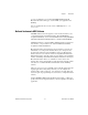
Important Information Warranty The SCXI chassis (SCXI-1000, SCXI-1000DC, and SCXI-1001) are warranted against defects in materials and workmanship for a period of one year from the date of shipment, as evidenced by receipts or other documentation. National Instruments will, at its option, repair or replace equipment that proves to be defective during the warranty period. This warranty includes parts and labor.
Conventions The following conventions are used in this manual: » The » symbol leads you through nested menu items and dialog box options to a final action. The sequence File»Page Setup»Options directs you to pull down the File menu, select the Page Setup item, and select Options from the last dialog box. This icon denotes a note, which alerts you to important information. This icon denotes a caution, which advises you of precautions to take to avoid injury, data loss, or a system crash.
Contents Chapter 1 Introduction About the SCXI Chassis ................................................................................................1-1 What You Need to Get Started ......................................................................................1-1 Software Programming Choices ....................................................................................1-2 NI-DAQ...........................................................................................................
Contents Appendix A Specifications Appendix B Common Questions Glossary Index Figures Figure 2-1. Figure 2-2. Figure 2-3. Figure 2-4. Figure 2-5. Figure 2-6. Figure 2-7. Figure 2-8. SCXI-1000 Front View Diagram.......................................................... 2-2 SCXI-1000DC Front View Diagram .................................................... 2-3 SCXI-1001 Front View Diagram.......................................................... 2-4 SCXI-1000 Rear View Diagram ..............................
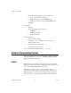
1 Introduction This manual describes the electrical and mechanical aspects of the SCXI-1000, SCXI-1000DC, and SCXI-1001 chassis and contains information concerning their operation. The SCXI chassis supply power to and contain control circuitry for the SCXI series of modules. The SCXI-1000 and SCXI-1000DC hold up to four modules. The SCXI-1001 holds up to 12 modules. This chapter describes the SCXI chassis, lists what you need to get started, and describes the optional software and equipment.
Chapter 1 Introduction – – One of the following, depending on your application: • Power cord (120, 220, or 240 VAC) • SCXI-1382 battery pack (SCXI-1000DC only) • SCXI-1383 (VDC) power supply (SCXI-1000DC only) A computer ❑ Software – NI-DAQ – One of the following software packages: • LabVIEW • LabWindows™/CVI™ • Measurement Studio ❑ Documentation – SCXI Chassis User Manual – Read Me First: Safety and Radio-Frequency Interference – SCXI Quick Start Guide – Documentation for your ha
Chapter 1 Introduction to your code. Whether you are using LabVIEW, LabWindows/CVI, Measurement Studio, VI Logger, or other ADEs, your application uses NI-DAQ. You can download the most recent version of NI-DAQ from ni.com/ downloads. National Instruments ADE Software LabVIEW features interactive graphics, a state-of-the-art interface, and a powerful graphical programming language.
Chapter 1 Introduction National Instruments Documentation The SCXI Chassis User Manual is one piece of the documentation set for the data acquisition and SCXI system. You could have any of several types of documents, depending on the hardware and software in the system. Use the documents you have as follows: SCXI Chassis User Manual • Getting Started with SCXI—Read this manual first.
Chapter 1 Introduction Optional Equipment NI provides a full line of modules that amplify, filter, isolate, and multiplex a wide variety of signal types, such as thermocouples, resistance temperature detectors (RTDs), strain gauges, high-voltage inputs, current inputs, analog outputs, and digital I/O signals. Cables and terminal blocks with screw terminals, BNC connectors, or thermocouple plugs are available to connect signals to the modules. Refer to the latest NI catalog and ni.
2 Configuring and Installing the SCXI Chassis This chapter contains instructions for configuring and installing the SCXI chassis. It describes the following: • Chassis address selection • Voltage and fuse selection • Chassis, modules, and accessories installation • Fan filter maintenance Chassis Description Table 2-1 describes the front view items shown in Figures 2-1, 2-2, and 2-3. Table 2-1.
Chapter 2 Configuring and Installing the SCXI Chassis 5 6 7 8 4 3 2 5 4 3 2 1 ADDRESS 1 9 ON 10 1 2 3 4 5 5 Address DIP Switches Reset Button Power Switch Indicator Light Front Panel Screws (flathead on some revisions) 7 6 8 6 Front Panel Screws (early revisions only) 7 Module Guides 8 Front Threaded Strips 9 Backplane 10 Slot 0/Power Supply Figure 2-1. SCXI-1000 Front View Diagram SCXI Chassis User Manual 2-2 ni.
Chapter 2 5 Configuring and Installing the SCXI Chassis 6 7 8 4 3 2 9 1 10 1 2 3 4 5 5 Address Selection Jumpers (behind front panel) Reset Button Power Switch Indicator Light Front Panel Screws (flathead on some revisions) 6 7 8 6 Front Panel Screws (early revisions only) 7 Module Guides 8 Front Threaded Strips 9 Backplane 10 Slot 0/Power Supply Figure 2-2.
Chapter 2 Configuring and Installing the SCXI Chassis 5 6 7 8 7 8 4 3 2 ADDRESS 5 4 3 2 1 1 ON 10 1 2 3 4 5 5 6 9 Address DIP Switches Reset Button Power Switch Indicator Light Front Panel Screws (flathead on some revisions) 6 7 8 9 10 Front Panel Screws (early revisions only) Module Guides Front Threaded Strips Backplane Slot 0/Power Supply Figure 2-3. SCXI-1001 Front View Diagram Tables 2-2 and 2-3 describe the rear view items shown in Figures 2-4, 2-5, and 2-6. Table 2-2.
Chapter 2 Configuring and Installing the SCXI Chassis Table 2-2.
Chapter 2 Configuring and Installing the SCXI Chassis 5 4 6 120Vac 7 3 8 5 1 1 2 9 1 2 3 4 5 Fans and Filters Fan Screws (each fan) Rear Threaded Strips Rear Connector Space Rear Panel Screws (flathead on some revisions) 6 7 8 9 Voltage Tumbler Power Entry Module Fuse (concealed) Backplane Fuses (behind fan) Figure 2-5. SCXI-1001 Rear View Diagram Table 2-3. SCXI-1000DC Chassis Rear View Items Item Description Power entry connector J1 Receptacle for power input; uses a 9.
Chapter 2 Configuring and Installing the SCXI Chassis 5 4 J1 6 + 7 3 6.3A 250V 8 F2 3.15A 250V 5 1 2 1 2 3 4 5 F1 Fan and Filter Fan Screws Rear Threaded Strips Rear Connector Space Rear Panel Screws (flathead on some revisions) 9 6 7 8 9 Power Entry Connector Power Input Fuse +5 VDC Internal Power Supply Fuse Backplane Fuses (behind fan) Figure 2-6.
Chapter 2 Configuring and Installing the SCXI Chassis Configuring the SCXI Chassis Configuring the chassis involves selecting a chassis or high-level data link control (HDLC) address, line voltage, and fuse value on any chassis. Note Refer to the Read Me First: Safety and Radio-Frequency Interference document before removing equipment covers or connecting or disconnecting any signal wires. Selecting Chassis Addresses These sections provide information about how to select addresses for the SCXI chassis.
Chapter 2 Configuring and Installing the SCXI Chassis 5 4 3 2 1 ON Chassis Default Address = 0 5 4 3 2 1 ON Address = 19 Figure 2-7. Address Setting Examples SCXI-1000DC Unless you are using multiple chassis and need to configure one or more SCXI chassis for a different address, you can skip this section, and the SCXI chassis retains the factory-default address of 0.
Chapter 2 Configuring and Installing the SCXI Chassis W1 W1 0 1 2 3 4 5 6 7 0 1 2 3 4 5 6 7 W2 W2 +8 +8 W3 W3 +16 Chassis Address 0 Factory Setting +16 Chassis Address 19 Example Setting Figure 2-8. SCXI-1000DC Chassis Address Jumper Settings Changing the Chassis Address While referring to Figures 2-2 and 2-6, complete the following steps to change the chassis address of the SCXI-1000DC: SCXI Chassis User Manual 1.
Chapter 2 Configuring and Installing the SCXI Chassis Selecting Voltage and Replacing the Fuse for the SCXI-1000 and SCXI-1001 If you ordered the chassis with the appropriate part number (the -0x extension of the kit part number corresponds to your geographical region), the voltage tumbler and fuse are correct for operation in your geographical region. Check the voltage on the voltage tumbler to ensure that you have the correct voltage tumbler setting and fuse.
Chapter 2 Configuring and Installing the SCXI Chassis Table 2-4. SCXI-1000/1001 Voltage Selection and Fuse Ratings by Region (Continued) SCXI Chassis Type SCXI-1001 Main Power Fuse Quantity Region/Voltage Main Power Fuse Type Backplane Fuse Quantity Backplane Fuse Type 100 V Japan 1 2.0 A 250 5 mm × 20 mm SLO-BLO 2 4 A 125 V LittleFuse R251 01.5 TI 120 V 1 1.6 A 250 5 mm × 20 mm SLO-BLO 2 4 A 125 V LittleFuse R251 01.5 TI 220 V Swiss 1 1.
Chapter 2 Configuring and Installing the SCXI Chassis Replacing the Power Entry Module Fuse Caution Disconnect all power before removing the cover. Complete the following steps to replace the power entry module fuse: 1. Power off the chassis. 2. Remove the power cord from the power entry module. 3. Using a flathead screwdriver, pry the door to the voltage selection tumbler open from the top. 4. Pull out the fuse drawer. 5. Remove the fuse. 6. Install the new fuse in the drawer. 7.
Chapter 2 Configuring and Installing the SCXI Chassis Complete the following steps to check or replace fuses: 1. Remove the appropriate fan and filter from the rear of the chassis by following the instructions in the Maintaining the Fan Filter section. Make sure to switch the power off and remove the power cord. 2. The fuse marked with a copper + on the backplane is for the positive analog supply, and the fuse marked with a copper – is for the negative analog supply.
Chapter 2 Configuring and Installing the SCXI Chassis 6. Push the fuse holder back into the housing and screw it clockwise until it is tight. 7. Reinsert the power cord. Replacing and Checking Backplane Fuses In addition to the power entry and the +5 V supply fuses, the analog supply lines on the backplane are fused at 1.5 A on the SCXI-1000DC chassis.
Chapter 2 Configuring and Installing the SCXI Chassis Installing the SCXI Chassis These sections provide information about installing the SCXI chassis. Installing the SCXI-1000 and SCXI-1001 Chassis Complete the following steps to install the SCXI-1000 and SCXI-1001 chassis: 1. If necessary, change the chassis address of the box by following the instructions in the Selecting Chassis Addresses section.
Chapter 2 Configuring and Installing the SCXI Chassis 4. Make sure the voltage of the power source is between 9.5 and 16 VDC. 5. Insert the power plug into the header J1. Revision A SCXI-1000DC chassis have screw terminals on the rear panel to connect the power source. Wire the power source to these screw terminals. Observe the correct polarity, as connecting the power source with the wrong polarity can cause permanent damage to the chassis.
Chapter 2 Configuring and Installing the SCXI Chassis Installing Rear Panels Complete the following steps to install rear panels: 1. Place the panel at the rear of the chassis between the two threaded strips. Align the panel so that the serial number faces into the chassis and the screw holes are on the right. 2. Using a flathead screwdriver, screw the two screws through the rear panel into the threaded strip holes.
A Specifications This appendix lists the specifications of the SCXI chassis. These are typical at 25 °C unless otherwise stated. Electrical Characteristics SCXI-1000/ 1000DC SCXI-1101 Tolerance limits include peaks +18.5 to +25 V +18.5 to +25 V Ripple (peak-to-peak) 1.5 V 1.5 V Max load 680 mA 2.04 A Tolerance limits include peaks –18.5 to –25 V –18.5 to –25 V Ripple (peak-to-peak) 1.5 V 1.5 V Max load 680 mA 2.04 A Tolerance limits include peaks +4.75 to +5.25 V +4.75 to +5.
Appendix A Specifications Maximum loads are the supply current for the entire chassis. Scaling the maximum power gives the allotted current per slot, as follows. Supplies SCXI-1000/1000DC SCXI-1001 V+ 170 mA 170 mA V– 170 mA 170 mA +5 V 50 mA 50 mA Source Power Requirements Max AC Current Line Voltage, 47–63 Hz SCXI-1000 SCXI-1001 120 VAC, ±10% 0.6 A 1.25 A 100 VAC, ±10% 0.5 A 1.25 A 240 VAC, ±10% 0.25 A 0.75 A 220 VAC, ±10% 0.25 A 0.75 A SCXI-1000DC Input voltage .............
Specifications Figure A-1.
Figure A-2. Physical Dimensions of the SCXI-1000 and SCXI-1000DC Appendix A Specifications SCXI Chassis User Manual A-4 ni.
Appendix A Specifications Environmental Operating temperature............................ 0 to 50 °C Storage temperature ............................... –20 to 70 °C Humidity ................................................ 10 to 90% RH, noncondensing Maximum altitude .................................. 2,000 meters Pollution Degree (indoor use only) ........
Appendix A Specifications CE Compliance The chassis meet the essential requirements of applicable European Directives, as amended for CE marking, as follows: Low-Voltage Directive (safety)..............73/23/EEC Electromagnetic Compatibility Directive (EMC) .....................................89/336/EEC Note Refer to the Declaration of Conformity (DoC) for this product for any additional regulatory compliance information. To obtain the DoC for this product, visit ni.com/hardref.
B Common Questions My chassis worked fine until I inadvertently removed and reinserted a module while the chassis was on. Now my chassis does not power on. What can I do? SCXI modules are not hot swapable, so you may have blown a fuse. Refer to Chapter 2, Configuring and Installing the SCXI Chassis, for information on fuse replacement. If replacing the fuse does not correct the problem, you may have damaged the digital bus circuitry or the SCXI module. Please contact NI Technical Support at ni.
Glossary Symbol Prefix Value p pico 10 –12 m milli 10–3 k kilo 103 Numbers/Symbols ° degrees – negative of, or minus Ω ohms ± plus or minus + positive of, or plus % percent +5 V (signal) +5 VDC source signal A A amperes A/D analog-to-digital AC alternating current C C Celsius © National Instruments Corporation G-1 SCXI Chassis User Manual
Glossary D D/A digital-to-analog DAQ data acquisition—(1) collecting and measuring electrical signals from sensors, transducers, and test probes or fixtures and processing the measurement data using a computer; (2) collecting and measuring the same kinds of electrical signals with A/D and/or DIO boards plugged into a computer, and possibly generating control signals with D/A and/or DIO boards in the same computer F F (1) Fahrenheit—a temperature measurement scale; (2) farad—a measurement unit of capac
Glossary K kg kilograms L lb pounds O oz ounces S s seconds SCXI Signal Conditioning eXtensions for Instrumentation V V volts VAC volts, alternating current VDC volts, direct current W W watts © National Instruments Corporation G-3 SCXI Chassis User Manual
Index Symbols chassis usage considerations, 2-7 fuse replacement and check procedure, backplane SCXI-1000 and SCXI-1001, 2-13 SCXI-1000DC, 2-15 fuse replacement for power entry module +5 VDC fuse replacement, SCXI-1000DC, 2-14 voltage selection for SCXI-1000 and SCXI-1001 procedure, 2-12 voltage selection and fuse ratings by region (table), 2-11 conventions used in the manual, iv +5 VDC fuse replacement, SCXI-1000DC, 2-14 A address selection, 2-8 jumper settings SCXI-1000 and SCXI-1001 (figure), 2-9 SCXI
Index optional equipment, 1-5 overview, 1-1 SCXI chassis descriptions front view diagrams SCXI-1000, 2-2 SCXI-1000DC, 2-3 SCXI-1001, 2-4 front view items (table), 2-1 rear view diagrams SCXI-1000, 2-5 SCXI-1000DC, 2-7 SCXI-1001, 2-6 rear view items (table) SCXI-1000 and 1001, 2-4 SCXI-1000DC, 2-6 SCXI modules troubleshooting and common questions, B-1 SCXI-1000 address selection, 2-8 jumper settings (figure), 2-9 front view diagram, 2-2 fuse replacement backplane fuse replacement and check procedure, 2-13 f
Index fuse replacement +5 VDC fuse replacement, 2-14 backplane fuse replacement and check procedure, 2-15 power entry fuse and +5 VDC, 2-14 installation, 2-16 physical dimensions (figure), A-4 rear view diagram, 2-7 rear view items (table), 2-6 source power requirements, A-2 SCXI-1001 address selection, 2-8 jumper settings (figure), 2-9 front view diagram, 2-4 fuse replacement backplane fuse replacement and check procedure, 2-13 fuse ratings by region (table), 2-11 power entry module, 2-13 installation, 2-