MXI TM MXI-4 Series User Manual MXI-4 Multi-System Extension Interface for PCI, CompactPCI, and PXI Bus Computers PCI-8331 PXI-8331 PCI-8336 PXI-8336 MXI-4 Series User Manual December 2003 Edition Part Number 370840A-01
Support Worldwide Technical Support and Product Information ni.
Important Information Warranty The PXI-PCI 8331 and 8336 hardware is warranted against defects in materials and workmanship for a period of one year from the date of shipment, as evidenced by receipts or other documentation. National Instruments will, at its option, repair or replace equipment that proves to be defective during the warranty period. This warranty includes parts and labor.
Compliance Compliance with FCC/Canada Radio Frequency Interference Regulations Determining FCC Class The Federal Communications Commission (FCC) has rules to protect wireless communications from interference. The FCC places digital electronics into two classes. These classes are known as Class A (for use in industrial-commercial locations only) or Class B (for use in residential or commercial locations). All National Instruments (NI) products are FCC Class A products.
Contents About This Manual Conventions ...................................................................................................................vii Related Documentation..................................................................................................viii Chapter 1 Introduction About the MXI-4 Series.................................................................................................1-1 Description and Features ..........................................................
Contents Appendix A Specifications Appendix B Common Questions Appendix C Technical Support and Professional Services Glossary Index MXI-4 Series User Manual vi ni.
About This Manual This manual describes the features, functions, and operation of the MXI-4 series of products. The four products in this series are the PCI-8331, PXI-8331, PCI-8336, and PXI-8336. The PXI-PCI 8331 and 8336 incorporate MXI-4 technology, which couples two physically separate PCI, CompactPCI, or PXI buses with a data link capable of 1.5 Gbit/s serial data rates. Conventions The following conventions appear in this manual: This icon denotes a note, which alerts you to important information.
About This Manual In this manual, whenever a PXI chassis is referenced, a CompactPCI chassis could be used instead. Note Related Documentation The following documents contain information that you might find helpful as you read this manual: MXI-4 Series User Manual • Set Up Your MXI-4 System • Your computer or chassis documentation • PXI Hardware Specification, Revision 2.1 • PXI Software Specification, Revision 2.1 • PCI Specification, Revision 2.
1 Introduction This chapter describes the MXI-4 series of products, lists what you need to get started, and explains how to unpack and set up your hardware. The four products in this series are the PCI-8331, PXI-8331, PCI-8336, and PXI-8336. For the remainder of this manual the term MXI-4 card will refer to any of the products in the MXI-4 series. MXI-4 cards must always be installed as either a pair of PXI cards or as a PCI card and a PXI card.
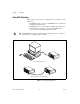
Chapter 1 Introduction Basic MXI-4 Systems MXI-4 cards are used in two basic configurations, both of which are shown in Figure 1-1: • A PCI MXI-4 in a PC, connected to a PXI MXI-4 in the controller slot of a PXI/CompactPCI chassis. • A PXI MXI-4 in a non-controller slot of a PXI/CompactPCI chassis with an embedded controller, connected to a PXI MXI-4 in the controller slot of another PXI/CompactPCI chassis.
Chapter 1 Introduction Larger MXI-4 Systems Using multiple MXI-4 dyads, large PCI/PXI/CompactPCI systems can be created. The PCI specification makes provisions for up to 255 bus segments to simultaneously exist in a PCI hierarchy and MXI-4 hardware provides everything needed to support those provisions. Notes Keep in mind that some chassis and PCs have more than one PCI bus segment.
Chapter 1 Introduction Daisy-Chain Configuration Star Configuration Figure 1-2. Star and Daisy Chain MXI-4 Configurations Adding PCI bridges, such as MXI-4, to a system can create a slight decrease in performance when communicating with devices behind the bridges. Note Although the distance between individual chassis is confined to a maximum of 10 meters for copper cables and 200 meters for fiber-optic cables, there is no limit to the total amount of cable in the system.
Chapter 1 Introduction What You Need to Get Started To set up and use your MXI-4 cards, you need the following: ❑ Two MXI-4 cards of the allowable pairings that comprise a MXI-4 dyad.
Chapter 1 Introduction To avoid such damage in handling the device, take the following precautions: • Ground yourself using a grounding strap or by holding a grounded object. • Touch the antistatic package to a metal part of the computer chassis before removing the device from the package. Remove the device from the package and inspect the device for loose components or any sign of damage. Notify NI if the device appears damaged in any way. Do not install a damaged device into the computer.
Hardware and Software Installation 2 This chapter explains how to install the MXI-4 software and hardware. Software Installation The software for your MXI-4 controller enables use of the MXI-4 Connection Monitor which is built into the MXI-4 hardware. This software enhances the product, allowing you to monitor your MXI-4 link, view information about the organization of your PXI system, and programmatically retrieve data about the link, chassis, and modules you have installed.
Chapter 2 Hardware and Software Installation Hardware Installation The following are general instructions for installing the MXI-4 cards. Consult your computer user manual or technical reference manual for specific instructions and warnings. Installing a PCI MXI-4 Card 1. Power off your computer, but leave it plugged in while installing the PCI MXI-4 card. The power cord grounds the chassis and protects it from electrical damage while you install the module.
Chapter 2 Hardware and Software Installation 2 1 3 1 2 PCI MXI-4 Card PCI Bus Card-Edge Connector 3 PCI Bus Slot Figure 2-1. Installing the PCI MXI-4 Installing a PXI MXI-4 Card Complete the following steps to install the PXI MXI-4 in your PXI or CompactPCI chassis. 1. Power off your PXI or CompactPCI chassis, but leave it plugged in while installing the PXI MXI-4 card. The power cord grounds the chassis and protects it from electrical damage while you install the module. 2.
Chapter 2 Hardware and Software Installation 3. Remove or open any doors or covers blocking access to the slot in which you intend to install the PXI MXI-4. 4. Touch the metal part of the case to discharge any static electricity that might be on your clothes or body. 5. Make sure the injector/ejector handle is in its downward position. Be sure to remove all connector packaging and protective caps from retaining screws on the module.
Chapter 2 Hardware and Software Installation 1 NI PX I-1 04 2 2 4 3 1 2 PXI/Compact PCI Chassis PXI MXI-4 Card 3 4 Ejector Handle in Down Position PXI/Compact PCI Slot 1 Figure 2-2. PXI MXI-4 Before Installation as Secondary Cabling 1. Connect the appropriate MXI-4 cable to both MXI-4 cards. If you are using a fiber-optic MXI-4 cable, be sure to remove the protective caps from the connectors. The cables have no polarity, so either end may be connected to either card.
Chapter 2 Hardware and Software Installation Powering Up the MXI-4 System 1. Power on all of the expansion chassis in any order you choose. 2. Power on the host, which could either be a PC or a CompactPCI/PXI chassis with an embedded controller. Typical PCI-PCI bridges are used to add PCI devices to a PCI hierarchy in which all the bridges and devices are contained within a single chassis.
Hardware and Software Overview 3 This chapter presents an overview of the hardware and software function of MXI-4 cards, and explains the operation of each functional unit. Hardware Overview Functional Overview The PCI specification places a limit on the number of PCI devices that can be placed on any single PCI bus segment in order to guarantee the electrical characteristics and timing of the bus.
Chapter 3 Hardware and Software Overview copper cable using one differential pair on that cable to transmit data, and the other pair to receive the data. National Instruments MXI-4 FPGA C P P P X C C I I I B u s Parallelto-Serial Converter Transmitter Port Serial Data Serial Connector/ Fiber-Optic Transceiver PCI/PXI Interface Port Serialto-Parallel Converter Receiver Port Serial Data Figure 3-1.
Chapter 3 Hardware and Software Overview MXI-4 Cable Options MXI-4 dyads are available with either copper or fiber-optic media connecting the MXI-4 cards. Copper cabled MXI-4 boards can span up to 10 meters, while fiber-optic cables provide up to 200 meters of separation between the cards. Table 3-1 shows the cables that are available from National Instruments: Table 3-1.
Chapter 3 Hardware and Software Overview You can determine how frequently retransmissions are occurring by enabling the Show PXI Bus Details attribute of your PXI system (refer to Figure 3-2). To set this attribute, right-click your PXI system in MAX and select the Show PXI Bus Details menu option. Figure 3-2. Show PXI Bus Details Attribute in Configuration Pop-Up MXI-4 Series User Manual 3-4 ni.
Chapter 3 Hardware and Software Overview With this attribute enabled, clicking on a PXI Bridge entry in MAX that corresponds to a MXI-4 link will display information about the link in the right-hand pane in MAX (refer to Figure 3-3). To update the information shown, click the Refresh button. Note In normal operation, the bridge retransmit count should be zero. Figure 3-3.
Chapter 3 Hardware and Software Overview MXI-4 Linked Chassis Status When your PXI system contains a chassis connected through MXI-4, MAX can show additional information about the chassis status depending on the state of the MXI-4 link. If there is a problem with the link or the chassis is not connected, MAX will display the chassis with a yellow exclamation point indicating a warning (refer to Figure 3-4). Figure 3-4. Chassis Status Indication in Configuration Tree MXI-4 Series User Manual 3-6 ni.
Chapter 3 Hardware and Software Overview To determine the cause of the warning, click the chassis in the MAX tree view and check the status bar text to determine what condition the software detected (refer to Figure 3-5). Figure 3-5. Chassis Status Indication in Status Bar of Right Pane View If MAX indicates that the MXI-4 connection has timed out, the MXI-4 card did not detect that it was connected to another MXI-4 card at power-up time.
A Specifications This appendix lists the system specifications for PCI MXI-4 and PXI MXI-4 cards. These specifications are typical at 25 °C, unless otherwise stated. Physical Dimensions PCI .................................................. 10.7 × 17.5 cm (4.2 × 6.9 in.) PXI .................................................. 10.0 × 16.0 cm (3.9 × 6.3 in.) Maximum cable lengths Copper............................................. 10 m Fiber-optic.......................................
Appendix A Specifications Environment Maximum altitude...................................2,000 m Pollution Degree .....................................2 Indoor use only Operating Environment Ambient temperature range ....................0 to 55 °C (tested in accordance with IEC-60068-2-1 and IEC-60068-2-2) Operating relative humidity....................10 to 90%, noncondensing (tested in accordance with IEC-60068-2-56) Storage Environment Ambient temperature range ....................
Appendix A Specifications Random Vibration Operating................................................ 5 to 500 Hz, 0.3 grms Nonoperating.......................................... 5 to 500 Hz, 2.4 grms (Tested in accordance with IEC-60068-2-64. Nonoperating test profile exceeds the requirements of MIL-PRF-28800F, Class 3.
Appendix A Specifications CE Compliance This product meets the essential requirements of applicable European Directives, as amended for CE marking, as follows: Low-Voltage Directive (safety)..............73/23/EEC Electromagnetic Compatibility Directive (EMC) .....................................89/336/EEC Refer to the Declaration of Conformity (DoC) for this product for any additional regulatory compliance information. To obtain the DoC for this product, visit ni.com/hardref.
B Common Questions This appendix lists common questions related to the use of the MXI-4 controllers.
Appendix B Common Questions impact of this situation in general, design a multi-chassis system layout such that there are a minimum of MXI-4 links between the host PC and PXI boards requiring large bandwidth. General Cabling What are the different cabling options for MXI-4? There are two different types of cables that can be used with MXI-4. The PCI/PXI-8331 uses a copper cable. The PCI/PXI-8336 uses a fiber-optic cable.
Appendix B Common Questions MXI-4 copper cables look like standard serial cables. Are they the same? No. Although MXI-4 copper cables use the same DB-9 connector as many RS-232 serial cables like those found on a regular PC, they are not compatible. RS-232 cables and MXI-4 cables cannot be interchanged. Also, never attempt to cable together a standard RS-232 serial port to the copper connector on a MXI-4 board. Doing so will result in damage to your hardware.
Appendix B Common Questions function will show up in the WDM listed under System devices as a PCI standard PCI-to-PCI bridge. The second function listing in the WDM will show up as a MXI-4 Connection Monitor when the correct MXI-4 driver is installed. If the MXI-4 software is not installed, the PCI-to-PCI function will still be detected and work correctly, but the MXI-4 Connection Monitor will be detected as an unknown device.
Appendix B Common Questions connected in series can be powered on in any order, except that you need to ensure that the last component powered on is the host PC or the chassis containing the host controller as previously mentioned. For more details, refer to the Powering Up the MXI-4 System section in Chapter 2, Hardware and Software Installation. What is the benefit of Universal PCI support with MXI-4? With Universal PCI support, MXI-4 now can be used in more types of PCI and PCI-X slots. Table B-1.
Technical Support and Professional Services C Visit the following sections of the National Instruments Web site at ni.com for technical support and professional services: • Support—Online technical support resources include the following: – Self-Help Resources—For immediate answers and solutions, visit our extensive library of technical support resources available in English, Japanese, and Spanish at ni.com/support.
Appendix C Technical Support and Professional Services • Calibration Certificate—If your product supports calibration, you can obtain the calibration certificate for your product at ni.com/calibration. If you searched ni.com and could not find the answers you need, contact your local office or NI corporate headquarters. Phone numbers for our worldwide offices are listed at the front of this manual. You also can visit the Worldwide Offices section of ni.
Glossary Symbol Prefix Value n nano 10 –9 µ micro 10 – 6 m milli 10 –3 k kilo 10 3 M mega 10 6 Symbols ° Degrees ≥ Equal or greater than ≤ Equal or less than % Percent B bus the group of conductors that interconnect individual circuitry in a computer. Typically, a bus is the expansion vehicle to which I/O or other devices are connected. Examples of PC buses are the AT bus, NuBus, Micro Channel, and EISA bus.
Glossary D device a plug-in instrument card or pad that can contain multiple channels and conversion devices. Plug-in boards and PCMCIA cards, which connect to your computer parallel port, are examples of devices. digital trigger a TTL level signal having two discrete levels—a high and a low level DMA direct memory access—a method by which data can be transferred to/from computer memory from/to a device or memory on the bus while the processor does something else.
Glossary PXI PCI eXtensions for Instrumentation. PXI is an open specification that builds off the CompactPCI specification by adding instrumentation-specific features.
Index A F additional MXI-4 configurations (figure), 1-4 fiber optic transceiver, 3-2 functional unit descriptions, 3-2 B H basic MXI-4 configurations (figure), 1-2 block diagram, 3-2 help, technical support, C-1 HSSDC (High-Speed Serial Data Connector Cable), 3-3 C cable options, 3-3 calibration certificate (NI resources), C-2 common questions, B-1 configuration, basic (figure), 1-2 configurations, additional daisy chain (figure), 1-4 star (figure), 1-4 conventions used in the manual, vii I install
Index R MXI-4 FPGA, 3-2 MXI-4 system definition, 1-1 description, 1-1 getting started, 1-5 related documentation, viii S safety specifications (table), A-3 serial connector, 3-2 serial-to-parallel converter, 3-2 software, 2-1 software (NI resources), C-1 specifications, A-1 electromagnetic compatibility, A-3 safety, A-3 support, technical, C-1 N National Instruments support and services, C-1 O overview functional unit descriptions, 3-2 hardware, 3-1 MXI-4 block diagram, 3-2 T technical support, C-1 t