NI Vision NI PCI-8254R User Manual IEEE 1394a Interface Device with Reconfigurable I/O NI PCI-8254R User Manual February 2007 371578D-01
Support Worldwide Technical Support and Product Information ni.
Important Information Warranty The NI PCI-8254R is warranted against defects in materials and workmanship for a period of one year from the date of shipment, as evidenced by receipts or other documentation. National Instruments will, at its option, repair or replace equipment that proves to be defective during the warranty period. This warranty includes parts and labor.
Compliance Compliance with FCC/Canada Radio Frequency Interference Regulations Determining FCC Class The Federal Communications Commission (FCC) has rules to protect wireless communications from interference. The FCC places digital electronics into two classes. These classes are known as Class A (for use in industrial-commercial locations only) or Class B (for use in residential or commercial locations). All National Instruments (NI) products are FCC Class A products.
Conventions The following conventions are used in this manual: » The » symbol leads you through nested menu items and dialog box options to a final action. The sequence File»Page Setup»Options directs you to pull down the File menu, select the Page Setup item, and select Options from the last dialog box. This icon denotes a note, which alerts you to important information. This icon denotes a caution, which advises you of precautions to take to avoid injury, data loss, or a system crash.
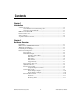
Contents Chapter 1 Introduction Software Overview ........................................................................................................1-1 Vision Builder for Automated Inspection .......................................................1-2 Vision Development Module ..........................................................................1-2 IEEE 1394 and NI 8254R ..............................................................................................1-3 Functional Overview...........
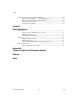
Contents Considerations When Connecting the Digital I/O......................................................... 2-12 Wiring an Isolated Input to a Sourcing Output Device................................... 2-12 Wiring an Isolated Output to an External Load .............................................. 2-13 Protecting Inductive Loads ............................................................................. 2-14 Transmission Line Effects ..................................................................
1 Introduction The NI PCI-8254R is a OHCI compliant IEEE 1394a interface device with reconfigurable I/O (RIO). The NI 8254R device ships with NI Vision Acquisition Software, which contains all of the drivers in the NI Vision product line. With NI Vision Acquisition Software, you can quickly and easily start your applications without having to program the device at the register level.
Chapter 1 Introduction Vision Builder for Automated Inspection NI Vision Builder for Automated Inspection (Vision Builder AI) is configurable machine vision software that you can use to prototype, benchmark, and deploy applications. Vision Builder AI does not require programming, but is scalable to powerful programming environments. Vision Builder AI allows you to easily configure and benchmark a sequence of visual inspection steps, as well as deploy the visual inspection system for automated inspection.
Chapter 1 Introduction LabVIEW VI creation wizard, Vision Assistant can create LabVIEW VI diagrams that perform the prototype you created in Vision Assistant. You can then use LabVIEW to add functionality to the generated VI. IEEE 1394 and NI 8254R The NI 8254R uses FireWire® (IEEE 1394) technology.
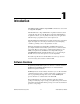
Chapter 1 Introduction V2 FPGA ISO In TTL In DSUB PCI CONN PCI Bridge Dust MITE CPLD TTL Out ISO Out Config ROM ISO Power Connection 1394 Conns 1394A Controller Power Supply +5 V, +1.5 V 1394 Power Conn Figure 1-1. NI 8254R Block Diagram Start Conditions The NI 8254R can start acquisitions in the following ways: • Software control—The NI 8254R supports software control of acquisition start. You can configure the NI 8254R to capture a fixed number of frames.
2 Hardware Overview Digital I/O The digital I/O functions on the NI 8254R are accessible through 2 TTL inputs, 10 TTL outputs, 13 isolated inputs, and 4 isolated outputs. You can use input signals as triggers, product selection ports, change detectors, or to read quadrature encoders. Uses for output signals include controlling camera reset and exposure, controlling strobe lighting, outputting inspection results, or communicating with PLCs.
Chapter 2 Hardware Overview Using National Instruments RIO hardware and the LabVIEW FPGA Module, you can define your hardware without in-depth knowledge of hardware design tools or hardware description languages (HDL). When the signal requirements change, the LabVIEW code can be modified and downloaded to the FPGA to change the I/O mix or type. This flexibility allows you to reuse the same hardware and software at no extra expense.
Chapter 2 Hardware Overview Table 2-1 summarizes the TTL inputs and outputs available on the NI 8254R. Table 2-1.
Chapter 2 Hardware Overview Table 2-2 summarizes the isolated inputs and outputs available on the NI 8254R. Table 2-2.
Chapter 2 Hardware Overview Trigger Inputs Trigger inputs are available from both TTL inputs and isolated inputs. You can use these trigger inputs to synchronize the NI 8254R with an external event, such as the assertion of a signal generated by a proximity sensor or a PLC, to indicate that an inspection item is passing in front of the camera. The NI 8254R uses this input to initiate a timed pulse that can be used for camera control, lighting control, encoder pulse counting, and result output timing.
Chapter 2 Hardware Overview If the trigger input is set to Immediate in LabVIEW or using a None status signal in C and Visual Basic, the pulse generation occurs as soon as the pulse mode is set to Start in LabVIEW or imaqIOPulseStart in C and Visual Basic. After generating a pulse, it immediately generates another pulse until the pulse generation is stopped.
Chapter 2 Hardware Overview Pulse Width Pulse width is the amount of time between the first (assertion) edge of a pulse and the second (deassertion) edge. Pulse width is configurable only in microseconds from 1 µs to 4,294,967,295 µs. Trigger Polarity Each pulse generator can be individually configured for rising or falling edge triggering. Even if multiple pulse generators are using the same trigger, each can have different polarities.
Chapter 2 Hardware Overview Trigger Change Detectors The NI 8254R is capable of detecting edges on various trigger lines and latching this information for future retrieval. This feature is useful for high-precision hardware-monitoring of the presence of external events without the need for software polling. You can arm for the detection of a rising edge, falling edge, or both on a supported trigger input line.
Chapter 2 Hardware Overview Based on the input to the product selection port, you can configure the application software to run the appropriate inspection sequence. For example, an upstream NI 8254R programmed for part classification might drive the product selection port of a downstream NI 8254R. Alternatively, a PLC with information about which part is being inspected can drive the product selection port of the NI 8254R.
Chapter 2 Hardware Overview General-Purpose Inputs The primary difference between general-purpose inputs and trigger inputs is that you cannot use general-purpose inputs to initiate a timed pulse generator. In an application, use the general-purpose inputs to get the status of the inputs at a given point and not to synchronize the NI 8254R with an external event.
Chapter 2 Hardware Overview Table 2-4. Fault Condition Behavior Shutdown Enabled Outputs Change to User-Defined States External Shutdown On Off Yes No Watchdog On Off Yes No Fault Condition The following sections describe each fault condition. Shutdown Shutdown mode is a software-enabled feature that, when activated, allows an external device to halt the NI 8254R processing operations. Additionally, Shutdown mode allows you to specify user-defined shutdown states for all fault conditions.
Chapter 2 Hardware Overview Use the Indicator Only option only to test the watchdog timer. If software becomes unresponsive, it cannot be relied upon to send notification to the host. Caution • Indicator Only—This option sends the expiration signal back to the development machine through software. True indicates an expired watchdog timer. False indicates an unexpired watchdog timer. The expiration signal that indicates an expired watchdog timer continues to assert until the watchdog timer is disarmed.
Chapter 2 Hardware Overview Sourcing Output Device V Vcc Input Current Limiter C NI 8254R Figure 2-5. Connecting isolated input to a sourcing output device Wiring an Isolated Output to an External Load The digital output circuit sources current to external loads, as shown in Figure 2-6. Caution Do not draw more than 100 mA from 24 V or 30 V isolated outputs. Do not draw more than 50 mA from 5 V isolated outputs. V Vcc Digital Output Load C NI 8254R Figure 2-6.
Chapter 2 Hardware Overview Protecting Inductive Loads When an inductive load, such as a relay or solenoid, is connected to an output, a large counter-electromotive force may occur at switching time due to energy stored in the inductive load. This flyback voltage can damage the outputs and the power supply. To limit flyback voltages at the inductive load, install a flyback diode across the load. Mount the flyback diode as close to the load as possible.
Chapter 2 Hardware Overview Transmission Line Effects Transmission line effects can degrade the signals on the I/O cables and cause instability. To minimize transmission line effects, use twisted pair wires with a characteristic impedance of 118 Ω to connect external signals to the 44-pin I/O D-SUB connector. Figure 2-8 shows connections to the 44-pin D-SUB connector that minimize transmission line effects.
3 Signal Connections The following diagram shows the connectors on the NI 8254R.
Chapter 3 Signal Connections Table 3-1 summarizes the functions of the connectors on the NI 8254R. Table 3-1.
Chapter 3 Signal Connections Table 3-2 summarizes the functions of the power connector terminals. Table 3-2. Power Connector Terminals Terminal Description V Isolated power (5 to 30 VDC) C Isolated common-mode signal IEEE 1394a Connector The IEEE 1394a connectors on the NI 8254R provide a reliable, high-frequency connection between the NI 8254R and up to two DCAM-compliant IEEE 1394 cameras. To access the IEEE 1394a connectors on the NI 8254R, use any standard 6-pin IEEE 1394 cable.
Chapter 3 Signal Connections Figure 3-2 illustrates the 44-pin D-SUB connector on the NI 8254R. 44 30 15 31 16 1 Figure 3-2. NI 8254R 44-Pin D-SUB Connector Table 3-3 lists pin numbers, signal names, and signal descriptions for the 44-pin D-SUB connector on the NI 8254R and the 37-pin terminal block. Caution Do not draw more than 500 mA combined from the V pins on the 44-pin D-SUB connector. Do not draw more than 100 mA from 24 V or 30 V isolated outputs.
Chapter 3 Signal Connections Table 3-3.
Chapter 3 Signal Connections Table 3-3.
Chapter 3 Signal Connections Table 3-3.
Chapter 3 Signal Connections Table 3-3.
Chapter 3 Signal Connections TRIG 0, TRIG 1, and TRIG 2 signals are not accessible through the standard 44- to 37-pin cable and I/O terminal block. Note NI Vision I/O Terminal Block and Prototyping Accessory Use the NI Vision I/O Terminal Block and Prototyping Accessory to troubleshoot and prototype digital I/O applications for the NI 8254R, the NI 8255R, and the NI CVS-1450 Series compact vision system.
Technical Support and Professional Services A Visit the following sections of the National Instruments Web site at ni.com for technical support and professional services: • Support—Online technical support resources at ni.
Appendix A Technical Support and Professional Services • Calibration Certificate—If your product supports calibration, you can obtain the calibration certificate for your product at ni.com/calibration. If you searched ni.com and could not find the answers you need, contact your local office or NI corporate headquarters. Phone numbers for our worldwide offices are listed at the front of this manual. You also can visit the Worldwide Offices section of ni.
Glossary A ADE Application development environment such as LabVIEW, Visual Basic, or Microsoft Visual C. B bandwidth The range of frequencies present in a signal, or the range of frequencies to which a measuring device can respond. C current The rate of flow of electric charge measured in amperes. D D-SUB A serial connector. DCAM Digital camera. development machine Machine used to develop an application. A development machine usually has and ADE installed on it.
Glossary FireWire A high-speed serial interface invented by Apple Computer in 1989, also known as IEEE 1394 or iLink. FPGA Field-programmable gate array. An FPGA is a semi-conductor device which contains a large quantity of gates (logic devices), which are not interconnected, and whose function is determined by a wiring list, which is downloaded to the FPGA.
Glossary PLC Programmable Logic Controller. An industrial computer used for factory automation, process control, and manufacturing systems. proximity sensor Optical sensor which toggles an electrical signal when an object passes near it. Q quadrature encoder An encoding technique for a rotating device where two tracks of information are placed on the device, with the signals on the tracks offset by 90 degrees from each other. This makes it possible to detect the direction of the motion.
Index A G acquisition window control, 1-4 general purpose outputs, 2-10 general-purpose I/O, 2-9 general-purpose inputs, 2-10 C cabling, 3-8 calibration certificate (NI resources), A-2 connector functions, 3-2 connectors, 3-2 2-position isolated output power, 3-2 general-purpose digital I/O, 3-3 IEEE 1394a, 3-3 conventions used in the manual, v H help, technical support, A-1 I I/O for fault conditions, 2-10 I/O for normal operation, 2-4 I/O terminal block, 3-8 IEEE 1394, 1-3 camera cables, 3-8 IEEE 13
Index N NI Vision Terminal Block and Prototyping Accessory, 3-9 National Instruments support and services, A-1 NI 1427 software programming choices NI Vision Builder for Automated Inspection, 1-2 NI Vision Development Module, 1-2 NI 8254R acquisition window control, 1-4 cabling, 3-8 connection considerations, 2-12 connector functions, 3-2 connectors, 3-2 digital I/O, 2-1 functional overview, 1-3 general-purpose I/O, 2-9 I/O for fault conditions, 2-10 I/O for normal operation, 2-4 IEEE 1394, 1-3 isolated
Index T W technical support, A-1 timed pulse output initiating, 2-5 overview, 2-5 training and certification (NI resources), A-1 transmission line effects, 2-15 trigger change detectors, 2-8 trigger inputs, 2-5 trigger polarity, 2-7 troubleshooting (NI resources), A-1 TTL inputs, 2-2 list of, 2-3 TTL outputs, 2-2 list of, 2-3 watchdog timer, 2-11 Web resources, A-1 wiring isolated input to sourcing output device, 2-12 isolated output to external load, 2-13 © National Instruments Corporation I-3 NI PC