PCI.
PCI.book Page 2 Wednesday, September 16, 1998 9:09 AM Internet Support E-mail: support@natinst.com FTP Site: ftp.natinst.com Web Address: http://www.natinst.
PCI.book Page 3 Wednesday, September 16, 1998 9:09 AM Important Information Warranty The PCI-6023E, PCI-6024E, and PCI-6025E boards are warranted against defects in materials and workmanship for a period of one year from the date of shipment, as evidenced by receipts or other documentation. National Instruments will, at its option, repair or replace equipment that proves to be defective during the warranty period. This warranty includes parts and labor.
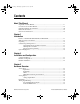
PCI.book Page v Wednesday, September 16, 1998 9:09 AM Contents About This Manual Organization of This Manual .........................................................................................xi Conventions Used in This Manual.................................................................................xii National Instruments Documentation ............................................................................xiii Related Documentation.........................................................
PCI.book Page vi Wednesday, September 16, 1998 9:09 AM Contents RTSI Triggers ................................................................................................. 3-8 Chapter 4 Signal Connections I/O Connector ................................................................................................................ 4-1 Analog Input Signal Overview...................................................................................... 4-8 Types of Signal Sources...........................
PCI.book Page vii Wednesday, September 16, 1998 9:09 AM Contents AIGATE Signal.................................................................................4-39 SISOURCE Signal ............................................................................4-40 Waveform Generation Timing Connections ...................................................4-40 WFTRIG Signal ................................................................................4-40 UPDATE* Signal.........................................
PCI.book Page viii Wednesday, September 16, 1998 9:09 AM Contents Glossary Index Figures Figure 1-1. The Relationship between the Programming Environment, NI-DAQ, and Your Hardware............................................................... 1-5 Figure 3-1. Figure 3-2. Figure 3-3. Figure 3-4. PCI-6023E, PCI-6024E, and PCI-6025E Block Diagram .................... 3-1 Dither .................................................................................................... 3-4 CONVERT* Signal Routing.
PCI.book Page ix Wednesday, September 16, 1998 9:09 AM Contents Figure 4-28. Figure 4-29. Figure 4-30. Figure 4-31. Figure 4-32. Figure 4-33. Figure 4-34. Figure 4-35. Figure 4-36. Figure 4-37. Figure 4-38. Figure 4-39. Figure 4-40. Figure 4-41. CONVERT* Output Signal Timing ......................................................4-39 SISOURCE Signal Timing....................................................................4-40 WFTRIG Input Signal Timing ....................................................
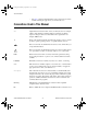
PCI.book Page xi Wednesday, September 16, 1998 9:09 AM About This Manual The PCI E Series boards are high-performance multifunction analog, digital, and timing I/O boards for PCI bus computers. Supported functions include analog input, analog output, digital I/O, and timing I/O. This manual describes the electrical and mechanical aspects of the PCI-6023E, PCI-6024E, and PCI-6025E boards from the PCI E Series product line and contains information concerning their operation and programming.
PCI.book Page xii Wednesday, September 16, 1998 9:09 AM About This Manual • The Index contains an alphabetical list of key terms and topics in this manual, including the page where you can find each one. Conventions Used in This Manual The following conventions are used in this manual: <> Angle brackets enclose the name of a key on the keyboard—for example, .
PCI.book Page xiii Wednesday, September 16, 1998 9:09 AM About This Manual SCXI SCXI stands for Signal Conditioning eXtensions for Instrumentation and is a National Instruments product line designed to perform front-end signal conditioning for National Instruments plug-in DAQ boards. National Instruments Documentation The PCI-6023E/6024E/6025E User Manual is one piece of the documentation set for your DAQ system.
PCI.book Page xiv Wednesday, September 16, 1998 9:09 AM About This Manual Related Documentation The following documents contain information you may find helpful: • DAQ-STC Technical Reference Manual • National Instruments Application Note 025, Field Wiring and Noise Considerations for Analog Signals • PCI Local Bus Specification Revision 2.
PCI.book Page 1 Wednesday, September 16, 1998 9:09 AM 1 Introduction This chapter describes the PCI-6023E, PCI-6024E, and PCI-6025E boards, lists what you need to get started, gives unpacking instructions, and describes the optional software and equipment. Features of the PCI-6023E, PCI-6024E, and PCI-6025E Thank you for buying a National Instruments PCI-6023E, PCI-6024E, or PCI-6025E board.
PCI.
PCI.book Page 3 Wednesday, September 16, 1998 9:09 AM Chapter 1 Introduction Software Programming Choices You have several options to choose from when programming your National Instruments DAQ and SCXI hardware. You can use National Instruments application software, NI-DAQ, or register-level programming. National Instruments Application Software ComponentWorks contains tools for data acquisition and instrument control built on NI-DAQ driver software.
PCI.book Page 4 Wednesday, September 16, 1998 9:09 AM Chapter 1 Introduction accessory products, except for the SCXI-1200. NI-DAQ has an extensive library of functions that you can call from your application programming environment.
PCI.book Page 5 Wednesday, September 16, 1998 9:09 AM Chapter 1 Conventional Programming Environment Introduction ComponentWorks, LabVIEW, LabWindows/CVI, or VirtualBench NI-DAQ Driver Software DAQ or SCXI Hardware Personal Computer or Workstation Figure 1-1. The Relationship between the Programming Environment, NI-DAQ, and Your Hardware Register-Level Programming The final option for programming any National Instruments DAQ hardware is to write register-level software.
PCI.
PCI.book Page 1 Wednesday, September 16, 1998 9:09 AM Installation and Configuration 2 This chapter explains how to install and configure your PCI-6023E, PCI-6024E, or PCI-6025E board. Software Installation Install your software before you install your board. Refer to the appropriate release notes indicated below for specific instructions on the software installation sequence. If you are using NI-DAQ, refer to your NI-DAQ release notes.
PCI.book Page 2 Wednesday, September 16, 1998 9:09 AM Chapter 2 Installation and Configuration You can modify data acquisition-related configuration settings, such as analog input range and mode, through application level software. Refer to Chapter 3, Hardware Overview, for more information about the various settings available for your board. These settings are changed and configured through software after you install your board.
PCI.book Page 1 Wednesday, September 16, 1998 9:09 AM 3 Hardware Overview This chapter presents an overview of the hardware functions on your board. Figure 3-1 shows a block diagram for the PCI-6023E, PCI-6024E, and PCI-6025E.
PCI.book Page 2 Wednesday, September 16, 1998 9:09 AM Chapter 3 Hardware Overview Analog Input The analog input section of each board is software configurable. The following sections describe in detail each of the analog input settings. Input Mode The boards have three different input modes—nonreferenced single-ended (NRSE) input, referenced single-ended (RSE) input, and differential (DIFF) input. The single-ended input configurations provide up to 16 channels.
PCI.book Page 3 Wednesday, September 16, 1998 9:09 AM Chapter 3 Hardware Overview 12-bit analog-to-digital converter (ADC) resolution. With the proper gain setting, you can use the full resolution of the ADC to measure the input signal. Table 3-2 shows the input range and precision according to the gain used. Table 3-2. Measurement Precision Input Range Precision * 0.5 -10 to +10V 4.88 mV 1.0 -5 to +5V 2.44 mV 10.0 -500 to +500 mV 244.14 µV 100.0 -50 to +50 mV 24.
PCI.book Page 4 Wednesday, September 16, 1998 9:09 AM Chapter 3 Hardware Overview LSBs 6.0 LSBs 6.0 4.0 4.0 2.0 2.0 0.0 0.0 -2.0 -2.0 -4.0 -4.0 -6.0 -6.0 0 100 200 300 400 0 500 a. Dither disabled; no averaging 100 200 300 400 500 b. Dither disabled; average of 50 acquisitions LSBs 6.0 LSBs 6.0 4.0 4.0 2.0 2.0 0.0 0.0 -2.0 -2.0 -4.0 -4.0 -6.0 -6.0 0 100 200 300 400 500 0 c. Dither enabled; no averaging 100 200 300 400 500 d.
PCI.book Page 5 Wednesday, September 16, 1998 9:09 AM Chapter 3 Hardware Overview multiplexer switches to channel 1 and the PGIA switches to a gain of 100, the new full-scale range is ±50 mV. The approximately 4 V step from 4 V to 1 mV is 4,000% of the new full-scale range. It may take as long as 100 µs for the circuitry to settle to 1 LSB after such a large transition. In general, this extra settling time is not needed when the PGIA is switching to a lower gain.
PCI.book Page 6 Wednesday, September 16, 1998 9:09 AM Chapter 3 Hardware Overview Digital I/O The PCI-6023E, PCI-6024, and PCI-6025E boards contain eight lines of digital I/O (DIO<0..7>) for general-purpose use. You can individually software-configure each line for either input or output. At system startup and reset, the digital I/O ports are all high impedance. The hardware up/down control for general-purpose counters 0 and 1 are connected onboard to DIO6 and DIO7, respectively.
PCI.book Page 7 Wednesday, September 16, 1998 9:09 AM Chapter 3 Hardware Overview RTSI Trigger <0..6> CONVERT* PFI<0..9> Sample Interval Counter TC GPCTR0_OUT Figure 3-3. CONVERT* Signal Routing This figure shows that CONVERT* can be generated from a number of sources, including the external signals RTSI<0..6> and PFI<0..9> and the internal signals Sample Interval Counter TC and GPCTR0_OUT.
PCI.book Page 8 Wednesday, September 16, 1998 9:09 AM Chapter 3 Hardware Overview UPDATE* signal as an output on the I/O connector, software can turn on the output driver for the PFI5/UPDATE* pin. Board and RTSI Clocks Many board functions require a frequency timebase to generate the necessary timing signals for controlling A/D conversions, DAC updates, or general-purpose signals at the I/O connector. These boards can use either its internal 20 MHz timebase or a timebase received over the RTSI bus.
PCI.book Page 9 Wednesday, September 16, 1998 9:09 AM Chapter 3 Hardware Overview DAQ-STC TRIG1 TRIG2 CONVERT* WFTRIG GPCTR0_SOURCE RTSI Switch RTSI Bus Connector UPDATE* Trigger 7 GPCTR0_GATE GPCTR0_OUT STARTSCAN AIGATE SISOURCE UISOURCE GPCTR1_SOURCE Clock GPCTR1_GATE switch RTSI_OSC (20 MHz) Figure 3-4. RTSI Bus Signal Connection Refer to the Timing Connections section of Chapter 4, Signal Connections, for a description of the signals shown in Figure 3-4.
PCI.book Page 1 Wednesday, September 16, 1998 9:09 AM 4 Signal Connections This chapter describes how to make input and output signal connections to your board via the I/O connector. The I/O connector for the PCI-6023 and PCI-6024E has 68 pins that you can connect to 68-pin accessories with the SH6868 shielded cable or the R6868 ribbon cable. You can connect your board to 50-pin signal accessories with the SH6850 shielded cable or R6850 ribbon cable.
PCI.
PCI.
PCI.book Page 4 Wednesday, September 16, 1998 9:09 AM Chapter 4 Signal Connections Table 4-1 shows the I/O connector signal descriptions for the PCI-6023E, PCI-6024E, and PCI-6025E. Table 4-1. I/O Connector Signal Descriptions Signal Name Reference Direction Description — — Analog Input Ground—These pins are the reference point for single-ended measurements in RSE configuration and the bias current return point for differential measurements.
PCI.book Page 5 Wednesday, September 16, 1998 9:09 AM Chapter 4 Signal Connections Table 4-1. I/O Connector Signal Descriptions (Continued) Signal Name Reference Direction Description SCANCLK DGND Output Scan Clock—This pin pulses once for each A/D conversion in scanning mode when enabled. The low-to-high edge indicates when the input signal can be removed from the input or switched to another signal.
PCI.book Page 6 Wednesday, September 16, 1998 9:09 AM Chapter 4 Signal Connections Table 4-1. I/O Connector Signal Descriptions (Continued) Signal Name Reference Direction DGND Input PFI5/UPDATE* Description PFI5/Update—As an input, this is one of the PFIs. Output PFI6/WFTRIG DGND As an output, this is the UPDATE* (AO Update) signal. A high-to-low edge on UPDATE* indicates that the analog output primary group is being updated for the PCI-6024 or PCI-6025.
PCI.book Page 7 Wednesday, September 16, 1998 9:09 AM Chapter 4 Signal Connections Table 4-2 shows the I/O signal summary for the PCI-6023E, PCI-6024E, and PCI-6025E. Table 4-2. I/O Signal Summary Signal Type and Direction Impedance Input/ Output Protection (Volts) On/Off Source (mA at V) Sink (mA at V) Rise Time (ns) Bias ACH<0..
PCI.book Page 8 Wednesday, September 16, 1998 9:09 AM Chapter 4 Signal Connections Table 4-2. I/O Signal Summary (Continued) Signal Name Signal Type and Direction Impedance Input/ Output Sink (mA at V) Rise Time (ns) Bias PFI3/GPCTR1_SOURCE DIO — V +0.5 3.5 at (V -0.4) cc 5 at 0.4 1.5 50 kΩ pu PFI4/GPCTR1_GATE DIO — Vcc +0.5 3.5 at (Vcc -0.4) 5 at 0.4 1.5 50 kΩ pu GPCTR1_OUT DO — — 3.5 at (V -0.4) cc 5 at 0.4 1.5 50 kΩ pu PFI5/UPDATE* DIO — V +0.5 3.5 at (V -0.
PCI.book Page 9 Wednesday, September 16, 1998 9:09 AM Chapter 4 Signal Connections Floating Signal Sources A floating signal source is not connected in any way to the building ground system but, rather, has an isolated ground-reference point. Some examples of floating signal sources are outputs of transformers, thermocouples, battery-powered devices, optical isolators, and isolation amplifiers. An instrument or device that has an isolated output is a floating signal source.
PCI.book Page 10 Wednesday, September 16, 1998 9:09 AM Chapter 4 Signal Connections Vin+ Programmable Gain Instrumentation Amplifier + + PGIA Vm - Vin- Measured Voltage Vm = [Vin+ - Vin-]* Gain Figure 4-3. Programmable Gain Instrumentation Amplifier (PGIA) In single-ended mode (RSE and NRSE), signals connected to ACH<0..15> are routed to the positive input of the PGIA. In differential mode, signals connected to ACH<0..
PCI.book Page 11 Wednesday, September 16, 1998 9:09 AM Chapter 4 Signal Connections gain setting of the amplifier. The amplifier output voltage is referenced to the ground for the board. Your board’s A/D converter (ADC) measures this output voltage when it performs A/D conversions. You must reference all signals to ground either at the source device or at the board.
PCI.book Page 12 Wednesday, September 16, 1998 9:09 AM Chapter 4 Signal Connections Signal Source Type Grounded Signal Source Floating Signal Source (Not Connected to Building Ground) Input Examples • Ungrounded Thermocouples • Signal conditioning with isolated outputs • Battery devices ACH(+) + V1 - ACH (-) Examples • Plug-in instruments with nonisolated outputs ACH(+) + + V1 - - + ACH (-) - R Differential (DIFF) AIGND AIGND See text for information on bias resistors.
PCI.book Page 13 Wednesday, September 16, 1998 9:09 AM Chapter 4 Signal Connections Differential Connection Considerations (DIFF Input Configuration) A differential connection is one in which the analog input signal has its own reference signal or signal return path. These connections are available when the selected channel is configured in DIFF input mode. The input signal is tied to the positive input of the PGIA, and its reference signal, or return, is tied to the negative input of the PGIA.
PCI.book Page 14 Wednesday, September 16, 1998 9:09 AM Chapter 4 Signal Connections Differential Connections for Ground-Referenced Signal Sources Figure 4-5 shows how to connect a ground-referenced signal source to a channel on the board configured in DIFF input mode.
PCI.book Page 15 Wednesday, September 16, 1998 9:09 AM Chapter 4 Signal Connections Differential Connections for Nonreferenced or Floating Signal Sources Figure 4-6 shows how to connect a floating signal source to a channel configured in DIFF input mode.
PCI.book Page 16 Wednesday, September 16, 1998 9:09 AM Chapter 4 Signal Connections of the PGIA and connect the negative side of the signal to AIGND as well as to the negative input of the PGIA, without any resistors at all. This connection works well for DC-coupled sources with low source impedance (less than 100 Ω). However, for larger source impedances, this connection leaves the differential signal path significantly out of balance.
PCI.book Page 17 Wednesday, September 16, 1998 9:09 AM Chapter 4 Signal Connections Single-Ended Connection Considerations A single-ended connection is one in which the board analog input signal is referenced to a ground that can be shared with other input signals. The input signal is tied to the positive input of the PGIA, and the ground is tied to the negative input of the PGIA. When every channel is configured for single-ended input, up to 16 analog input channels are available.
PCI.book Page 18 Wednesday, September 16, 1998 9:09 AM Chapter 4 Signal Connections Single-Ended Connections for Floating Signal Sources (RSE Configuration) Figure 4-7 shows how to connect a floating signal source to a channel configured for RSE mode. ACH Floating Signal Source Programmable Gain Instrumentation Amplifier + + Vs PGIA - + Input Multiplexers - AISENSE Measured Voltage Vm - AIGND I/O Connector Selected Channel in RSE Configuration Figure 4-7.
PCI.book Page 19 Wednesday, September 16, 1998 9:09 AM Chapter 4 Signal Connections Figure 4-8 shows how to connect a grounded signal source to a channel configured for NRSE mode. ACH+ GroundReferenced Signal Source + Vs + - Programmable Gain Instrumentation Amplifier PGIA + ACHCommonMode Noise and Ground Potential Measured Voltage Vm - + V cm - Input Multiplexers AISENSE AIGND I/O Connector Selected Channel in DIFF Configuration Figure 4-8.
PCI.book Page 20 Wednesday, September 16, 1998 9:09 AM Chapter 4 Signal Connections Analog Output Signal Connections ♦ PCI-6024E and PCI-6025E The analog output signals are DAC0OUT, DAC1OUT, and AOGND. DAC0OUT and DAC1OUT are not available on the PCI-6023E. DAC0OUT is the voltage output signal for analog output channel 0. DAC1OUT is the voltage output signal for analog output channel 1. AOGND is the ground reference signal for both analog output channels and the external reference signal.
PCI.book Page 21 Wednesday, September 16, 1998 9:09 AM Chapter 4 Signal Connections Digital I/O Signal Connections All Boards All boards have digital I/O signals DIO<0..7> and DGND. DIO<0..7> are the signals making up the DIO port, and DGND is the ground reference signal for the DIO port. You can program all lines individually to be inputs or outputs. Figure 4-10 shows signal connections for three typical digital I/O applications. +5 V LED DIO<4..7> TTL Signal DIO<0..
PCI.book Page 22 Wednesday, September 16, 1998 9:09 AM Chapter 4 Signal Connections switch shown in the figure. Digital output applications include sending TTL signals and driving external devices such as the LED shown in the figure. PCI-6025E Only The PCI-6025E board uses an 82C55A PPI to provide an additional 24 lines of digital I/O that represent three 8-bit ports: PA, PB, and PC. Each port can be programmed as an input or output port.
PCI.book Page 23 Wednesday, September 16, 1998 9:09 AM Chapter 4 Signal Connections In Figure 4-11, port A of one PPI is configured for digital output, and port B is configured for digital input. Digital input applications include receiving TTL signals and sensing external device states such as the state of the switch in Figure 4-11. Digital output applications include sending TTL signals and driving external devices such as the LED shown in Figure 4-11.
PCI.book Page 24 Wednesday, September 16, 1998 9:09 AM Chapter 4 Signal Connections Digital I/O Power-up State ♦ (PCI-6025E Only) The PCI-6025E contains bias resistors that control the state of the digital I/O lines PA<0..7>,PB<0..7>,PC<0..7> at power up. Each digital I/O line is configured as an input, pulled high by a 100 kΩ bias resistor. You can change individual lines from pulled up to pulled down by adding your own external resistors. This section describes the procedure.
PCI.book Page 25 Wednesday, September 16, 1998 9:09 AM Chapter 4 2. Signal Connections Using the following formula, calculate the largest possible load to maintain a logic low level of 0.4 V and supply the maximum driving current: V = I * RL ⇒ RL = V/I, where: V = 0.4 V ; Voltage across RL I = 46 µA + 10 µA ; 4.6 V across the 100 kΩ pull-up resistor and 10 µA maximum leakage current Therefore: ; 0.4 V/56 µA RL = 7.1 kΩ This resistor value, 7.1 kΩ, provides a maximum of 0.
PCI.book Page 26 Wednesday, September 16, 1998 9:09 AM Chapter 4 Signal Connections Table 4-4. Signal Names Used in Timing Diagrams (Continued) Name Type Description ACK* Input OBF* Output Output Buffer Full—A low signal on this handshaking line indicates that data has been written to the port. INTR Output Interrupt Request—This signal becomes high when the 82C55A requests service during a data transfer. The appropriate interrupt enable bits must be set to generate this signal.
PCI.
PCI.book Page 28 Wednesday, September 16, 1998 9:09 AM Chapter 4 Signal Connections Mode 1 Output Timing Timing specifications for an output transfer in mode 1 are as follows: T3 WR* T4 OBF* T1 T6 INTR T5 ACK* DATA T2 Name Description Minimum Maximum T1 WR* = 0 to INTR = 0 — 250 T2 WR* = 1 to Output — 200 T3 WR* = 1 to OBF* = 0 — 150 T4 ACK* = 0 to OBF* = 1 — 150 T5 ACK* Pulse Width 100 — — 150 T6 ACK* = 1 to INTR = 1 All timing values are in nanoseconds. Figure 4-14.
PCI.
PCI.book Page 30 Wednesday, September 16, 1998 9:09 AM Chapter 4 Signal Connections Power Connections Two pins on the I/0 connector supply +5 V from the computer power supply via a self-resetting fuse. The fuse will reset automatically within a few seconds after the overcurrent condition is removed. These pins are referenced to DGND and can be used to power external digital circuitry. • ! Caution Power rating +4.65 to +5.
PCI.book Page 31 Wednesday, September 16, 1998 9:09 AM Chapter 4 Signal Connections PFI0/TRIG1 PFI2/CONVERT* TRIG1 Source CONVERT* Source DGND I/O Connector Figure 4-16. Timing I/O Connections Programmable Function Input Connections There are a total of 13 internal timing signals that you can externally control from the PFI pins. The source for each of these signals is software-selectable from any of the PFIs when you want external control.
PCI.book Page 32 Wednesday, September 16, 1998 9:09 AM Chapter 4 Signal Connections will depend upon the particular timing signal being controlled. The detection requirements for each timing signal are listed within the section that discusses that individual signal. In edge-detection mode, the minimum pulse width required is 10 ns. This applies for both rising-edge and falling-edge polarity settings. There is no maximum pulse-width requirement in edge-detect mode.
PCI.book Page 33 Wednesday, September 16, 1998 9:09 AM Chapter 4 Signal Connections TRIG1 TRIG2 Don't Care STARTSCAN CONVERT* Scan Counter 3 2 1 0 2 2 2 1 0 Figure 4-18. Typical Pretriggered Acquisition SCANCLK Signal SCANCLK is an output-only signal that generates a pulse with the leading edge occurring approximately 50 to 100 ns after an A/D conversion begins.
PCI.book Page 34 Wednesday, September 16, 1998 9:09 AM Chapter 4 Signal Connections V OH V OL tw tw t w = 600 ns or 5 µs Figure 4-20. EXTSTROBE* Signal Timing TRIG1 Signal Any PFI pin can externally input the TRIG1 signal, which is available as an output on the PFI0/TRIG1 pin. Refer to Figures 4-17 and 4-18 for the relationship of TRIG1 to the DAQ sequence. As an input, the TRIG1 signal is configured in the edge-detection mode.
PCI.book Page 35 Wednesday, September 16, 1998 9:09 AM Chapter 4 Signal Connections tw tw = 50-100 ns Figure 4-22. TRIG1 Output Signal Timing The board also uses the TRIG1 signal to initiate pretriggered DAQ operations. In most pretriggered applications, the TRIG1 signal is generated by a software trigger. Refer to the TRIG2 signal description for a complete description of the use of TRIG1 and TRIG2 in a pretriggered DAQ operation.
PCI.book Page 36 Wednesday, September 16, 1998 9:09 AM Chapter 4 Signal Connections Figures 4-23 and 4-24 show the input and output timing requirements for the TRIG2 signal. tw Rising-edge polarity Falling-edge polarity t w = 10 ns minimum Figure 4-23. TRIG2 Input Signal Timing tw tw = 50-100 ns Figure 4-24. TRIG2 Output Signal Timing STARTSCAN Signal Any PFI pin can externally input the STARTSCAN signal, which is available as an output on the PFI7/STARTSCAN pin.
PCI.book Page 37 Wednesday, September 16, 1998 9:09 AM Chapter 4 Signal Connections STARTSCAN will be deasserted toff after the last conversion in the scan is initiated. This output is set to tri-state at startup. Figures 4-25 and 4-26 show the input and output timing requirements for the STARTSCAN signal. tw Rising-edge polarity Falling-edge polarity t w = 10 ns minimum Figure 4-25. STARTSCAN Input Signal Timing tw STARTSCAN t w = 50-100 ns a.
PCI.book Page 38 Wednesday, September 16, 1998 9:09 AM Chapter 4 Signal Connections A counter on your board internally generates the STARTSCAN signal unless you select some external source. This counter is started by the TRIG1 signal and is stopped either by software or by the sample counter. Scans generated by either an internal or external STARTSCAN signal are inhibited unless they occur within a DAQ sequence.
PCI.book Page 39 Wednesday, September 16, 1998 9:09 AM Chapter 4 Signal Connections tw t w = 50-150 ns Figure 4-28. CONVERT* Output Signal Timing The sample interval counter on the board normally generates the CONVERT* signal unless you select some external source. The counter is started by the STARTSCAN signal and continues to count down and reload itself until the scan is finished. It then reloads itself in preparation for the next STARTSCAN pulse.
PCI.book Page 40 Wednesday, September 16, 1998 9:09 AM Chapter 4 Signal Connections SISOURCE Signal Any PFI pin can externally input the SISOURCE signal, which is not available as an output on the I/O connector. The onboard scan interval counter uses the SISOURCE signal as a clock to time the generation of the STARTSCAN signal. You must configure the PFI pin you select as the source for the SISOURCE signal in the level-detection mode.
PCI.book Page 41 Wednesday, September 16, 1998 9:09 AM Chapter 4 Signal Connections externally triggered by another PFI. The output is an active high pulse with a pulse width of 50 to 100 ns. This output is set to tri-state at startup. Figures 4-30 and 4-31 show the input and output timing requirements for the WFTRIG signal. tw Rising-edge polarity Falling-edge polarity t w = 10 ns minimum Figure 4-30. WFTRIG Input Signal Timing tw tw = 50-100 ns Figure 4-31.
PCI.book Page 42 Wednesday, September 16, 1998 9:09 AM Chapter 4 Signal Connections Figures 4-32 and 4-33 show the input and output timing requirements for the UPDATE* signal. tw Rising-edge polarity Falling-edge polarity t w = 10 ns minimum Figure 4-32. UPDATE* Input Signal Timing tw t w = 300-350 ns Figure 4-33. UPDATE* Output Signal Timing The DACs are updated within 100 ns of the leading edge. Separate the UPDATE* pulses with enough time that new data can be written to the DAC latches.
PCI.book Page 43 Wednesday, September 16, 1998 9:09 AM Chapter 4 Signal Connections tp tw tw t p = 50 ns minimum t w = 23 ns minimum Figure 4-34. UISOURCE Signal Timing The maximum allowed frequency is 20 MHz, with a minimum pulse width of 23 ns high or low. There is no minimum frequency limitation. Either the 20 MHz or 100 kHz internal timebase normally generates the UISOURCE signal unless you select some external source.
PCI.book Page 44 Wednesday, September 16, 1998 9:09 AM Chapter 4 Signal Connections tp tw tw t p = 50 ns minimum t w = 23 ns minimum Figure 4-35. GPCTR0_SOURCE Signal Timing The maximum allowed frequency is 20 MHz, with a minimum pulse width of 23 ns high or low. There is no minimum frequency limitation. The 20 MHz or 100 kHz timebase normally generates the GPCTR0_SOURCE signal unless you select some external source.
PCI.book Page 45 Wednesday, September 16, 1998 9:09 AM Chapter 4 Signal Connections Figure 4-36 shows the timing requirements for the GPCTR0_GATE signal. tw Rising-edge polarity Falling-edge polarity t w = 10 ns minimum Figure 4-36. GPCTR0_GATE Signal Timing in Edge-Detection Mode GPCTR0_OUT Signal This signal is available only as an output on the GPCTR0_OUT pin. The GPCTR0_OUT signal reflects the terminal count (TC) of general-purpose counter 0.
PCI.book Page 46 Wednesday, September 16, 1998 9:09 AM Chapter 4 Signal Connections GPCTR1_SOURCE Signal Any PFI pin can externally input the GPCTR1_SOURCE signal, which is available as an output on the PFI3/GPCTR1_SOURCE pin. As an input, the GPCTR1_SOURCE signal is configured in the edge-detection mode. You can select any PFI pin as the source for GPCTR1_SOURCE and configure the polarity selection for either rising or falling edge.
PCI.book Page 47 Wednesday, September 16, 1998 9:09 AM Chapter 4 Signal Connections As an output, the GPCTR1_GATE signal monitors the actual gate signal connected to general-purpose counter 1. This is true even if the gate is being externally generated by another PFI. This output is set to tri-state at startup. Figure 4-39 shows the timing requirements for the GPCTR1_GATE signal. tw Rising-edge polarity Falling-edge polarity t w = 10 ns minimum Figure 4-39.
PCI.book Page 48 Wednesday, September 16, 1998 9:09 AM Chapter 4 Signal Connections leave the DIO7 pin free for general use. Figure 4-41 shows the timing requirements for the GATE and SOURCE input signals and the timing specifications for the OUT output signals of your board.
PCI.book Page 49 Wednesday, September 16, 1998 9:09 AM Chapter 4 Signal Connections arrangement results in an uncertainty of one source clock period with respect to unsynchronized gating sources. The OUT output timing parameters are referenced to the signal at the SOURCE input or to one of the internally generated clock signals on the boards. Figure 4-41 shows the OUT signal referenced to the rising edge of a source signal.
PCI.book Page 50 Wednesday, September 16, 1998 9:09 AM Chapter 4 Signal Connections The following recommendations apply for all signal connections to your board: • Separate board signal lines from high-current or high-voltage lines. These lines can induce currents in or voltages on the board signal lines if they run in parallel paths at a close distance.
PCI.book Page 1 Wednesday, September 16, 1998 9:09 AM 5 Calibration This chapter discusses the calibration procedures for your board. If you are using the NI-DAQ device driver, that software includes calibration functions for performing all of the steps in the calibration process. Calibration refers to the process of minimizing measurement and output voltage errors by making small circuit adjustments.
PCI.book Page 2 Wednesday, September 16, 1998 9:09 AM Chapter 5 Calibration vary with time and temperature. It is better to self-calibrate when the board is installed in the environment in which it will be used. Self-Calibration Your board can measure and correct for almost all of its calibration-related errors without any external signal connections. Your National Instruments software provides a self-calibration method.
PCI.book Page 3 Wednesday, September 16, 1998 9:09 AM Chapter 5 Calibration Other Considerations The CalDACs adjust the gain error of each analog output channel by adjusting the value of the reference voltage supplied to that channel. This calibration mechanism is designed to work only with the internal 10 V reference. Thus, in general, it is not possible to calibrate the analog output gain error when using an external reference.
PCI.book Page 1 Wednesday, September 16, 1998 9:09 AM A Specifications This appendix lists the specifications of PCI-6023E, PCI-6024E, and PCI-6025E boards. These specifications are typical at 25° C unless otherwise noted. Analog Input Input Characteristics Number of channels ............................... 16 single-ended or 8 differential (software-selectable per channel) Type of ADC.......................................... Successive approximation Resolution .........................................
PCI.book Page 2 Wednesday, September 16, 1998 9:09 AM Appendix A Specifications Overvoltage protection Powered On Powered Off ACH<0..15> ± 42 ± 35 AISENSE ± 40 ± 25 FIFO buffer size......................................512 S Data transfers ..........................................DMA, interrupts, programmed I/O DMA modes ...........................................Scatter-gather (Single transfer, demand transfer) Configuration memory size ....................
PCI.book Page 3 Wednesday, September 16, 1998 9:09 AM Appendix A Specifications Transfer Characteristics Relative accuracy ................................... ±0.5 LSB typ dithered, ±1.5 LSB max undithered DNL ....................................................... ±0.5 LSB typ, ±1.0 LSB max No missing codes ................................... 12 bits, guaranteed Offset error Pregain error after calibration ......... ±12 µV max Pregain error before calibration ......
PCI.book Page 4 Wednesday, September 16, 1998 9:09 AM Appendix A Specifications Dynamic Characteristics Bandwidth Signal Bandwidth Small (–3 dB) 500 kHz Large (1% THD) 225 kHz Settling time for full scale step ...............5 µs max to ±1.0 LSB accuracy System noise (LSBrms, not including quantization) Gain Dither Off Dither On 0.5 to 10 0.1 0.6 100 0.7 0.8 Crosstalk .................................................–60 dB, DC to 100 kHz Stability Recommended warm-up time.................
PCI.book Page 5 Wednesday, September 16, 1998 9:09 AM Appendix A Specifications Type of DAC.......................................... Double buffered, multiplying FIFO buffer size .................................... none Data transfers ......................................... DMA, interrupts, programmed I/O DMA modes...........................................
PCI.book Page 6 Wednesday, September 16, 1998 9:09 AM Appendix A Specifications Voltage Output Range ......................................................± 10 V Output coupling ......................................DC Output impedance...................................0.1 Ω max Current drive...........................................±5 mA max Protection................................................Short-circuit to ground Power-on state ........................................
PCI.book Page 7 Wednesday, September 16, 1998 9:09 AM Appendix A Specifications DIO<0..7> Digital logic levels Level Min Max Input low voltage 0V 0.8 V Input high voltage 2V 5V Input low current (Vin = 0 V) — Input high current (Vin = 5 V) — –320 µ A Output low voltage (IOL = 24 mA) — 0.4 V Output high voltage (IOH = 13 mA) 4.35 V — 10 µA Power-on state ........................................ Input (High-Z), 50 kΩ pull up to +5VDC Data transfers .....................................
PCI.book Page 8 Wednesday, September 16, 1998 9:09 AM Appendix A Specifications PB<0..7>.................................................Input (High-Z), 100 kΩ pull up to +5VDC PC<0..7>.................................................Input (High-Z), 100 kΩ pull up to +5VDC Data transfers ..........................................Interrupts, programmed I/O Timing I/O Number of channels................................2 up/down counter/timers, 1 frequency scaler Resolution ................................
PCI.book Page 9 Wednesday, September 16, 1998 9:09 AM Appendix A Specifications Pulse width............................................. 10 ns min RTSI Trigger lines ........................................... 7 Calibration Interval ................................................... 1 year Onboard calibration reference Level ............................................... 5.000 V (±3.5 mV) (actual value stored in EEPROM) Temperature coefficient .................. ±5 ppm/°C max Long-term stability ....
PCI.book Page 1 Wednesday, September 16, 1998 9:09 AM B Custom Cabling and Optional Connectors This appendix describes the various cabling and connector options for the boards. Custom Cabling National Instruments offers cables and accessories for you to prototype your application or to use if you frequently change board interconnections.
PCI.book Page 2 Wednesday, September 16, 1998 9:09 AM Appendix B Custom Cabling and Optional Connectors ♦ PCI-6025E AMP 100-position IDC male connector (part number 1-750913-9) AMP backshell, 0.50 max O.D. cable (part number 749081-1) AMP backshell, 0.55 max O.D. cable, (part number 749854-1) Optional Connectors Figure B-1 shows the pin assignments for the 68-pin E Series connector. This connector is available when you use the SH6868 or R6868 cable assemblies with the PCI-6023E and PCI-6024E.
PCI.
PCI.book Page 4 Wednesday, September 16, 1998 9:09 AM Appendix B Custom Cabling and Optional Connectors Figure B-2 shows the pin assignments for the 68-pin extended digital input connector. This is the other 68-pin connector available when you use the SH1006868 cable assembly with the PCI-6025E.
PCI.book Page 5 Wednesday, September 16, 1998 9:09 AM Appendix B Custom Cabling and Optional Connectors Figure B-3 shows the pin assignments for the 50-pin E Series connector. This connector is available when you use the SH6850 or R6850 cable assemblies with the PCI-6023E and PCI-6024E. It is also one of the two 50-pin connectors available when you use the RI005050 cable assembly with the PCI-6025E.
PCI.book Page 6 Wednesday, September 16, 1998 9:09 AM Appendix B Custom Cabling and Optional Connectors Figure B-4 shows the pin assignments for the 50-pin extended digital input connector. This is the other 50-pin connector available when you use the R1005050 cable assembly with the PCI-6025E.
PCI.book Page 1 Wednesday, September 16, 1998 9:09 AM C Common Questions This appendix contains a list of commonly asked questions and their answers relating to usage and special features of your board. General Information What is the DAQ-STC? The DAQ-STC is the System Timing Control application-specific integrated circuit (ASIC) designed by National Instruments and is the backbone of the PCI E Series boards. The DAQ-STC contains seven 24-bit counters and three 16-bit counters.
PCI.book Page 2 Wednesday, September 16, 1998 9:09 AM Appendix C Common Questions Installation and Configuration How do I set the base address for a my board? The base address of your board is assigned automatically through the PCI bus protocol. This assignment is completely transparent to you. What jumpers should I be aware of when configuring my PCI E Series board? The PCI E Series boards are jumperless and switchless.
PCI.book Page 3 Wednesday, September 16, 1998 9:09 AM Appendix C Common Questions Can I synchronize a one-channel analog input data acquisition with a one-channel analog output waveform generation on my PCI E Series board? Yes. One way to accomplish this is to use the waveform generation timing pulses to control the analog input data acquisition. To do this, follow steps 1 through 4 below, in addition to the usual steps for data acquisition and waveform generation configuration. 1.
PCI.book Page 4 Wednesday, September 16, 1998 9:09 AM Appendix C Common Questions are 24-bit counters (unlike the 16-bit counters on boards without the DAQ-STC). If you are using the NI-DAQ language interface or LabWindows/CVI, the answer is no, the counter/timer applications that you wrote previously will not work with the DAQ-STC. You must use the GPCTR functions; ICTR and CTR functions will not work with the DAQ-STC.
PCI.book Page 5 Wednesday, September 16, 1998 9:09 AM Appendix C Common Questions may have pull-up or pull-down resistors connected to them as shown in Table 4-2. These resistors weakly pull the output to either a logic high or logic low state. For example, DIO(0) will be in the high impedance state after power on, and Table 4-2 shows that there is a 50 kΩ pull-up resistor. This pull-up resistor will set the DIO(0) pin to a logic high when the output is in a high impedance state.
PCI.book Page 1 Wednesday, September 16, 1998 9:09 AM Customer Communication D For your convenience, this appendix contains forms to help you gather the information necessary to help us solve your technical problems and a form you can use to comment on the product documentation. When you contact us, we need the information on the Technical Support Form and the configuration form, if your manual contains one, about your system configuration to answer your questions as quickly as possible.
PCI.book Page 2 Wednesday, September 16, 1998 9:09 AM Fax-on-Demand Support Fax-on-Demand is a 24-hour information retrieval system containing a library of documents on a wide range of technical information. You can access Fax-on-Demand from a touch-tone telephone at 512 418 1111. E-Mail Support (Currently USA Only) You can submit technical support questions to the applications engineering team through e-mail at the Internet address listed below.
PCI.book Page 3 Wednesday, September 16, 1998 9:09 AM Technical Support Form Photocopy this form and update it each time you make changes to your software or hardware, and use the completed copy of this form as a reference for your current configuration. Completing this form accurately before contacting National Instruments for technical support helps our applications engineers answer your questions more efficiently.
PCI.book Page 5 Wednesday, September 16, 1998 9:09 AM PCI-6023E/6024E/6025E Hardware and Software Configuration Form Record the settings and revisions of your hardware and software on the line to the right of each item. Complete a new copy of this form each time you revise your software or hardware configuration, and use this form as a reference for your current configuration.
PCI.book Page 7 Wednesday, September 16, 1998 9:09 AM Documentation Comment Form National Instruments encourages you to comment on the documentation supplied with our products. This information helps us provide quality products to meet your needs. Title: PCI-6023E/6024E/6025E User Manual Edition Date: October 1998 Part Number: 322072A-01 Please comment on the completeness, clarity, and organization of the manual.
PCI.
PCI.book Page 2 Wednesday, September 16, 1998 9:09 AM Glossary A/D analog-to-digital ADC analog-to-digital converter—an electronic device, often an integrated circuit, that converts an analog voltage to a digital number ADC resolution the resolution of the ADC, which is measured in bits. An ADC with 16 bits has a higher resolution, and thus a higher degree of accuracy, than a 12-bit ADC.
PCI.book Page 3 Wednesday, September 16, 1998 9:09 AM Glossary base address a memory address that serves as the starting address for programmable registers. All other addresses are located by adding to the base address. BIOS basic input/output system—BIOS functions are the fundamental level of any PC or compatible computer. BIOS functions embody the basic operations needed for successful use of the computer’s hardware resources.
PCI.
PCI.book Page 5 Wednesday, September 16, 1998 9:09 AM Glossary dB decibel—the unit for expressing a logarithmic measure of the ratio of two signal levels: dB=20log10 V1/V2, for signals in volts DC direct current DC coupled allowing the transmission of both AC and DC signals DGND digital ground signal DIFF differential mode differential input an analog input consisting of two terminals, both of which are isolated from computer ground, whose difference is measured digital port See port.
PCI.book Page 6 Wednesday, September 16, 1998 9:09 AM Glossary EXTSTROBE external strobe signal F FIFO first-in first-out memory buffer—the first data stored is the first data sent to the acceptor. FIFOs are often used on DAQ devices to temporarily store incoming or outgoing data until that data can be retrieved or output.
PCI.book Page 7 Wednesday, September 16, 1998 9:09 AM Glossary GPCTR0_OUT general purpose counter 0 output signal GPCTR0_SOURCE general purpose counter 0 clock source signal GPCTR0_UP_DOWN general purpose counter 0 up down GPCTR1_GATE general purpose counter 1 gate signal GPCTR1_OUT general purpose counter 1 output signal GPCTR1_SOURCE general purpose counter 1 clock source signal GPCTR1_UP_DOWN general purpose counter 1 up down GPIB General Purpose Interface bus, synonymous with HP-IB.
PCI.book Page 8 Wednesday, September 16, 1998 9:09 AM Glossary input bias current the current that flows into the inputs of a circuit input impedance the resistance and capacitance between the input terminals of a circuit input offset current the difference in the input bias currents of the two inputs of an instrumentation amplifier instrument driver a set of high-level software functions that controls a specific GPIB, VXI, or RS-232 programmable instrument or a specific plug-in DAQ board.
PCI.book Page 9 Wednesday, September 16, 1998 9:09 AM Glossary L LabVIEW laboratory virtual instrument engineering workbench LED light-emitting diode library a file containing compiled object modules, each comprised of one of more functions, that can be linked to other object modules that make use of these functions. NIDAQMSC.LIB is a library that contains NI-DAQ functions.
PCI.book Page 10 Wednesday, September 16, 1998 9:09 AM Glossary noise an undesirable electrical signal—Noise comes from external sources such as the AC power line, motors, generators, transformers, fluorescent lights, soldering irons, CRT displays, computers, electrical storms, welders, radio transmitters, and internal sources such as semiconductors, resistors, and capacitors. Noise corrupts signals you are trying to send or receive.
PCI.
PCI.
PCI.book Page 13 Wednesday, September 16, 1998 9:09 AM Glossary RTSI bus real-time system integration bus—the National Instruments timing bus that connects DAQ boards directly, by means of connectors on top of the boards, for precise synchronization of functions S s seconds S samples sample counter the clock that counts the output of the channel clock, in other words, the number of samples taken.
PCI.
PCI.
PCI.
PCI.
PCI.
PCI.book Page 3 Wednesday, September 16, 1998 9:09 AM Index field wiring considerations, 4-49 to 4-50 floating signal sources description, 4-9 differential connections, 4-15 to 4-16 single-ended connections (RSE configuration), 4-18 FREQ_OUT signal description (table), 4-6 general-purpose timing signal connections, 4-49 signal summary (table), 4-8 frequently asked questions. See questions and answers.
PCI.
PCI.
PCI.
PCI.
PCI.
PCI.