User.
User.book Page 2 Tuesday, April 14, 1998 10:20 AM Internet Support E-mail: support@natinst.com FTP Site: ftp.natinst.com Web Address: http://www.natinst.
User.book Page 3 Tuesday, April 14, 1998 10:20 AM Important Information Warranty The PCI-4451/4452 is warranted against defects in materials and workmanship for a period of one year from the date of shipment, as evidenced by receipts or other documentation. National Instruments will, at its option, repair or replace equipment that proves to be defective during the warranty period. This warranty includes parts and labor.
User.book Page v Tuesday, April 14, 1998 10:20 AM Contents About This Manual Organization of This Manual .........................................................................................ix Conventions Used in This Manual.................................................................................x National Instruments Documentation ............................................................................xi Related Documentation.................................................................
User.book Page vi Tuesday, April 14, 1998 10:20 AM Contents Device and RTSI Clocks................................................................................. 3-11 Selecting Sample/Update Clock Frequency .................................................................. 3-12 Device Configuration Issues.......................................................................................... 3-13 Chapter 4 Signal Connections I/O Connectors..............................................................
User.book Page vii Tuesday, April 14, 1998 10:20 AM Contents Chapter 5 Calibration Loading Calibration Constants ......................................................................................5-1 Self-Calibration..............................................................................................................5-2 External Calibration .......................................................................................................5-2 Traceable Recalibration .........................
User.book Page viii Tuesday, April 14, 1998 10:20 AM Contents Figures Figure 3-1. Figure 3-2. Figure 3-3. Figure 3-4. Figure 3-5. Figure 3-6. Figure 3-7. Figure 3-8. Digital Function Block Diagram........................................................... 3-1 Analog Function Block Diagram .......................................................... 3-2 Below-Low-Level Triggering Mode..................................................... 3-7 Above-High-Level Triggering Mode...................................
User.book Page ix Tuesday, April 14, 1998 10:20 AM About This Manual This manual describes the electrical and mechanical aspects of the PCI-4451 and PCI-4452 devices and contains information concerning their operation. Unless otherwise noted, the text applies to both devices. The PCI-4451 and PCI-4452 are high-performance, high-accuracy analog input/output (I/O) devices for the PCI bus. These devices also support digital I/O (DIO) functions, counter/timer functions, and external trigger functions.
User.book Page x Tuesday, April 14, 1998 10:20 AM About This Manual • The Glossary contains an alphabetical list and description of terms used in this manual, including abbreviations, acronyms, metric prefixes, mnemonics, and symbols. • The Index contains an alphabetical list of key terms and topics in this manual, including the page where you can find each one.
User.book Page xi Tuesday, April 14, 1998 10:20 AM About This Manual National Instruments Documentation The PCI-4451/4452 User Manual is one piece of the documentation set for your DAQ system. You could have any of several types of manuals depending on the hardware and software in your system. Use the manuals you have as follows: • Software documentation—You may have both application software and NI-DAQ software documentation.
User.book Page 1 Tuesday, April 14, 1998 10:20 AM 1 Introduction This chapter describes the PCI-4451 and PCI-4452 devices, lists what you need to get started, explains how to unpack your devices, and describes the optional software and optional equipment. The PCI-4451/4452 are high-performance, high-accuracy analog I/O devices for the PCI bus. These devices are members of the PCI-DSA series and are specifically designed for demanding dynamic signal acquisition applications.
User.
User.book Page 3 Tuesday, April 14, 1998 10:20 AM Chapter 1 Introduction Software Programming Choices There are several options to choose from to program and use your National Instruments device. You can use LabVIEW for Windows, LabWindows/CVI for Windows, VirtualBench-DSA, ComponentWorks, and Measure. National Instruments Application Software LabVIEW and LabWindows/CVI are innovative program development software packages for data acquisition and control applications.
User.book Page 4 Tuesday, April 14, 1998 10:20 AM Chapter 1 Introduction application you can use to make measurements as you would with a standard dynamic analyzer. ComponentWorks contains tools for data acquisition and instrument control built on NI-DAQ driver software. ComponentWorks provides a higher-level programming interface for building virtual instruments with Visual Basic, Visual C++, Borland Delphi, and Microsoft Internet Explorer.
User.book Page 5 Tuesday, April 14, 1998 10:20 AM Chapter 1 Introduction • To create your own accessories, you can use an AMP 68-pin right-angle PWB receptacle header, part number 787254-1.
User.book Page 1 Tuesday, April 14, 1998 10:20 AM 2 Installation and Configuration This chapter explains how to install and configure your PCI-4451/4452 device. Software Installation Note Install your software before you install your PCI-4451/4452 device. If you are using NI-DAQ, refer to your NI-DAQ release notes. Find the installation section for your operating system and follow the instructions given there.
User.book Page 2 Tuesday, April 14, 1998 10:20 AM Chapter 2 Installation and Configuration 7. Check the installation. 8. Replace the cover. 9. Plug in and turn on your computer. The PCI-4451/4452 device is now installed. You are now ready to configure your software. Device Configuration The PCI-4451/4452 devices are completely software configurable. However, you must perform two types of configuration—bus-related and data acquisition-related.
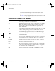
User.book Page 1 Tuesday, April 14, 1998 10:20 AM 3 Hardware Overview This chapter presents an overview of the hardware functions on your PCI-4451/4452 device. Figure 3-1 shows a block diagram of the digital functions. Figure 3-2 shows a block diagram of the analog functions. The two function blocks connect through the analog mezzanine bus.
PCI-4451/4452 User Manual † 3-2 ATTEN MUX Control 0 dB/20 dB ATTEN MUX3 0 dB/20 dB ATTEN MUX2 PCI-4451 only †† AC/DC MUX Control INPUT/CAL MUX Control PCI-4452 only AC/DC Coupling MUX3 INPUT/CAL MUX3 AC/DC Coupling MUX2 0 dB/20 dB ATTEN MUX1 AC/DC Coupling MUX1 INPUT/CAL MUX1 Gain Control DIFF Gain AMP DIFF Gain AMP DIFF Gain AMP DIFF Gain AMP Analog Overrange Detect LP Filter LP Filter LP Filter LP Filter Gain/Offset Calibration † † Trigger Control EEPROM General Control Digit
User.book Page 3 Tuesday, April 14, 1998 10:20 AM Chapter 3 Hardware Overview Analog Input The analog input section of each PCI-4451/4452 device is software configurable. You can select different analog input configurations through application software. The following sections describe in detail each of the analog input categories. Input Mode The PCI-4451/4452 devices use differential (DIFF) inputs. You can configure the input as a referenced single ended (SE) channel using the BNC-2140 DSA accessory.
User.book Page 4 Tuesday, April 14, 1998 10:20 AM Chapter 3 Hardware Overview Table 3-1. Actual Range and Measurement Precision Linear Gain Gain Input Range Precision1 0.1 –20 dB ±42.4 V2 3.0518 mV2 0.316 –10 dB ±31.6 V 965.05 µV 1.0 0 dB ±10.0 V 305.18 µV 3.16 10 dB ±3.16 V 96.505 µV 10 20 dB ±1.00 V 30.518 µV 31.6 30 dB ±0.316 V 9.6505 µV 100 40 dB ±0.100 V 3.0518 µV 316 50 dB ±31.6 mV 965.05 nV 1000 60 dB ±10.0 mV 305.
User.book Page 5 Tuesday, April 14, 1998 10:20 AM Chapter 3 ! Caution Hardware Overview If you exceed the rated input voltages, you can damage the computer and the connected equipment. Analog Output The analog output section of the PCI-4451 device is software-configurable. You can select different analog output configurations through application software designed to control the PCI-4451. The following sections describe in detail each of the analog output categories.
User.book Page 6 Tuesday, April 14, 1998 10:20 AM Chapter 3 Hardware Overview Table 3-2. Actual Range and Measurement Precision Attenuation Linear Attenuation dB Range Precision1 1.0 0 dB ±10.0 V 305.18 µV 10 20 dB ±1.00 V 30.158 µV 100 40 dB ±0.100 V 3.0518 µV ∞ ∞ dB 0V 0V 1 The value of 1 LSB of the 16-bit DAC; that is, the voltage increment corresponding to a change of one count in the DAC 16-bit count. See Appendix A, Specifications, for absolute maximum ratings.
User.book Page 7 Tuesday, April 14, 1998 10:20 AM Chapter 3 Hardware Overview you can configure the analog input section to acquire a given number of samples after the analog input signal crosses a specific threshold. As another example, you can configure the analog output section to generate an output waveform whenever the analog input signal crosses a specific threshold. Due to the nature of delta-sigma converters, the triggering circuits operate on the digital output of the converter.
User.book Page 8 Tuesday, April 14, 1998 10:20 AM Chapter 3 Hardware Overview In above-high-level triggering mode, the trigger is generated when the signal value is greater than highValue. LowValue is unused. highValue Trigger Figure 3-4. Above-High-Level Triggering Mode In inside-region triggering mode, the trigger is generated when the signal value is between the lowValue and the highValue. highValue lowValue Trigger Figure 3-5.
User.book Page 9 Tuesday, April 14, 1998 10:20 AM Chapter 3 Hardware Overview In low-hysteresis triggering mode, the trigger is generated when the signal value is less than lowValue, with the hysteresis specified by highValue. highValue lowValue Trigger Figure 3-7. Low-Hysteresis Triggering Mode You can use digital triggering through the RTSI bus and the external digital 50-pin connector using any one of the eight available programmable function input (PFI) pins.
User.book Page 10 Tuesday, April 14, 1998 10:20 AM Chapter 3 Hardware Overview DAQ-STC TRIG1 TRIG2 CONVERT* Trigger 7 RTSI Switch RTSI Bus Connector UPDATE* WFTRIG GPCTR0_SOURCE GPCTR0_GATE GPCTR0_OUT GPCTR1_SOURCE GPCTR1_GATE RTSI_OSC (20 MHz) Clock switch Figure 3-8. RTSI Bus Signal Connection Refer to the Chapter 4, Signal Connections for a description of the signals shown in Figure 3-8.
User.book Page 11 Tuesday, April 14, 1998 10:20 AM Chapter 3 Hardware Overview Timing Signal Routing The DAQ-STC provides a flexible interface for connecting timing signals to other devices or to external circuitry. Your PCI-4451/4452 device uses the RTSI bus to interconnect timing signals between devices, and uses the PFI pins on the I/O connector to connect the device to external circuitry.
User.book Page 12 Tuesday, April 14, 1998 10:20 AM Chapter 3 Hardware Overview A PCI-4451/4452 device can use either its internal 20 MHz timebase or a timebase received over the RTSI bus. In addition, if you configure the device to use the internal timebase, you can program the device to drive its internal timebase over the RTSI bus to another device that you program to receive this timebase signal.
User.book Page 13 Tuesday, April 14, 1998 10:20 AM Chapter 3 Hardware Overview Device Configuration Issues Selecting a sample rate that is less than two times the frequency of a band of interest can lead you to believe the board is functioning improperly. By undersampling the signal, you could receive what appears to be a DC signal. This situation is due to the sharp antialiasing filters that remove frequency components above the sampling frequency.
User.book Page 1 Tuesday, April 14, 1998 10:20 AM 4 Signal Connections This chapter describes how to make input and output connections to your PCI-4451/4452 device via the analog I/O and digital I/O connectors of the device. The analog I/O connector for the PCI-4451/4452 connects to the BNC-2140 DSA accessory through the SHC68-C68-A1 shielded cable. You can access the analog I/O of the PCI-4451/4452 using standard BNC connectors on the BNC-2140.
User.book Page 2 Tuesday, April 14, 1998 10:20 AM Chapter 4 Signal Connections Analog I/O Connector Signal Descriptions Figure 4-1 shows the analog pin connections for the PCI-4451/4452.
User.book Page 3 Tuesday, April 14, 1998 10:20 AM Chapter 4 Signal Connections Table 4-1. Analog I/O Connector Pin Assignment Signal Name Reference Direction Description +ACH<0..3> AIGND Input +Analog Input Channel 0 through 3—The PCI-4451 uses +ACH<0..1> and the PCI-4452 uses +ACH<0..3>. −ACH<0..3> AIGND Input −Analog Input Channel 0 through 3—The PCI-4451 uses −ACH<0..1> and the PCI-4452 uses −ACH<0..3>.
User.book Page 4 Tuesday, April 14, 1998 10:20 AM Chapter 4 Signal Connections Table 4-2. Analog I/O Signal Summary Signal Name Signal Type and Direction Impedance Input/ Output Protection (Volts) On/Off Source (mA at V) Sink (mA at V) Rise Time (ns) Bias +ACH<0..3> AI 1 MΩ in parallel with 50 pF to AIGND ±42.4 V/±42.4 V† — — — ±100 pA −ACH<0..3> AI 1 MΩ in parallel with 50 pF to AIGND ±42.4 V/±42.
User.book Page 5 Tuesday, April 14, 1998 10:20 AM Chapter 4 Signal Connections Digital I/O Connector Signal Descriptions Figure 4-2 shows the digital pin connections for the PCI-4451/4452.
User.book Page 6 Tuesday, April 14, 1998 10:20 AM Chapter 4 Signal Connections Table 4-3. Digital I/O Connector Pin Assignment Signal Name Reference Direction Description DIO<0..7> DGND Input or Output Digital I/O channels 0 through 7—Channels 6 and 7 can control the up/down signal of general-purpose counters 0 and 1, respectively. DGND — — Digital Ground—This pin supplies the reference for the digital signals at the I/O connector as well as the +5 VDC supply.
User.book Page 7 Tuesday, April 14, 1998 10:20 AM Chapter 4 Signal Connections Table 4-3. Digital I/O Connector Pin Assignment (Continued) Signal Name Reference Direction Description GPCTR1_OUT DGND Output General-Purpose Counter 1 Output PFI6/WFTRIG DGND Input PFI6/Waveform Trigger—As an input, this is one of the PFIs. Output As an output, this is the WFTRIG signal. In timed analog output sequences, a low-to-high transition indicates the initiation of the waveform generation.
User.book Page 8 Tuesday, April 14, 1998 10:20 AM Chapter 4 Signal Connections Table 4-4. Digital I/O Signal Summary Signal Type and Direction Impedance Input/ Output DGND DIO — +5 V DIO 0.15 Ω DIO<0..7> DIO RESERVED1 Signal Name Protection (Volts) On/Off Source (mA at V) Sink (mA at V) Rise Time (ns) Bias — — — — — Short-circuit to ground 1A — — — — Vcc +0.5 13 at (Vcc −0.4) 24 at 0.4 1.1 50 kΩ pu DO — — — — — 50 kΩ pu EXTSTROBE* DO — — 3.5 at (Vcc −0.
User.book Page 9 Tuesday, April 14, 1998 10:20 AM Chapter 4 Signal Connections Analog Input Signal Connections The analog input signals for the PCI-4451/4452 devices are +ACH<0..3>, −ACH<0..3>, and AIGND. The +ACH<0..1> signals are tied to the two analog input channels of your PCI-4451, and ±ACH<0..3> are tied to the four analog input channels of your PCI-4452 device. ! Caution Exceeding the differential and common-mode input ranges distorts your input signals.
User.book Page 10 Tuesday, April 14, 1998 10:20 AM Chapter 4 Signal Connections amplifier output voltage is referenced to the ground for the device. Your PCI-4451/4452 device A/D converter (ADC) measures this output voltage when it performs A/D conversions. Connection of analog input signals to your PCI-4451/4452 device depends on the configuration of the input signal sources.
User.book Page 11 Tuesday, April 14, 1998 10:20 AM Chapter 4 Signal Connections Analog Output Signal Connections The analog output signals for the PCI-4451 device are +DAC0OUT, −DAC0OUT, +DAC1OUT, -DAC1OUT, and AOGND. +DAC0OUT and −DAC0OUT are the plus and minus voltage output signals for analog output channel 0. +DAC1OUT and −DAC1OUT are the plus and minus voltage output signal, for analog output channel 1. AOGND is a ground-reference signal for both analog output channels.
User.book Page 12 Tuesday, April 14, 1998 10:20 AM Chapter 4 Signal Connections terminals is still equal to the desired signal. If the minus side is grounded, the plus voltage is equal to the signal. Conversely, if the plus side is grounded, the minus voltage is equal to the negative of the signal. In all cases, the difference is equal to the signal. Connection of analog output signals from your PCI-4451 device depends on the configuration of the devices receiving the signals.
User.book Page 13 Tuesday, April 14, 1998 10:20 AM Chapter 4 Signal Connections Figure 4-5 shows signal connections for three typical digital I/O applications. +5 V LED DIO<4..7> TTL Signal DIO<0..3> +5 V Switch DGND I/O Connector Figure 4-5. Digital I/O Connections Figure 4-5 shows DIO<0..3> configured for digital input and DIO<4..7> configured for digital output.
User.book Page 14 Tuesday, April 14, 1998 10:20 AM Chapter 4 Signal Connections Digital Power Connections Four pins on the digital I/O connector supply +5 V from the computer power supply via a self-resetting fuse. The fuse will reset automatically within a few seconds after the overcurrent condition is removed. These pins are referenced to DGND and you can use them to power external digital circuitry. • ! Caution Power rating +4.65 to +5.
User.book Page 15 Tuesday, April 14, 1998 10:20 AM Chapter 4 Signal Connections As an input, you can individually configure each PFI for edge or level detection and for polarity selection as well. You can use the polarity selection for any of the timing signals, but the edge or level detection depends upon the particular timing signal being controlled. The detection requirements for each timing signal are listed within the section that discusses that individual signal.
User.book Page 16 Tuesday, April 14, 1998 10:20 AM Chapter 4 Signal Connections Pretriggered data acquisition allows you to view data that is acquired before the trigger of interest in addition to data acquired after the trigger. Figure 4-7 shows a typical pretriggered acquisition sequence. The description for each signal shown in these figures is included later in this chapter. TRIG1 TRIG2 Don't Care Don't Care CONVERT* Sample Counter 3 2 1 0 2 2 2 1 0 Figure 4-7.
User.book Page 17 Tuesday, April 14, 1998 10:20 AM Chapter 4 Signal Connections PFI1/TRIG2 (PRETRIG) Signal Any PFI pin can externally input the PFI/1TRIG2 (PRETRIG) signal, which is available as an output on the PFI1/TRIG2 (PRETRIG) pin. Refer to Figure 4-7 for the relationship of PFI1/TRIG2 to the acquisition sequence. As an input, the PFI1/TRIG2 signal is configured in edge-detection mode.
User.book Page 18 Tuesday, April 14, 1998 10:20 AM Chapter 4 Signal Connections EXTSTROBE* Signal EXTSTROBE* is an output-only signal that generates either a single pulse or a sequence of eight pulses in the hardware-strobe mode. An external device can use this signal to latch signals or to trigger events. In single-pulse mode, software controls the level of the EXTSTROBE* signal. A 10 µs and a 1.2 µs clock is available for generating a sequence of eight pulses in hardware-strobe mode.
User.book Page 19 Tuesday, April 14, 1998 10:20 AM Chapter 4 Signal Connections General-Purpose Timing Signal Connections The general-purpose timing signals are GPCTR0_SOURCE, GPCTR0_GATE, GPCTR0_OUT, GPCTR0_UP_DOWN, GPCTR1_SOURCE, GPCTR1_GATE, GPCTR1_OUT, GPCTR1_UP_DOWN, and FREQ_OUT. GPCTR0_SOURCE Signal Any PFI pin can externally input the GPCTR0_SOURCE signal, which is available as an output on the PFI8/GPCTR0_SOURCE pin.
User.book Page 20 Tuesday, April 14, 1998 10:20 AM Chapter 4 Signal Connections GPCTR0_GATE Signal Any PFI pin can externally input the GPCTR0_GATE signal, which is available as an output on the PFI9/GPCTR0_GATE pin. As an input, the GPCTR0_GATE signal is configured in the edge-detection mode. You can select any PFI pin as the source for GPCTR0_GATE and configure the polarity selection for either rising or falling edge.
User.book Page 21 Tuesday, April 14, 1998 10:20 AM Chapter 4 Signal Connections GPCTR1_SOURCE Signal Any PFI pin can externally input the GPCTR1_SOURCE signal, which is available as an output on the PFI3/GPCTR1_SOURCE pin. As an input, the GPCTR1_SOURCE signal is configured in edge-detection mode. You can select any PFI pin as the source for GPCTR1_SOURCE and configure the polarity selection for either rising or falling edge.
User.book Page 22 Tuesday, April 14, 1998 10:20 AM Chapter 4 Signal Connections As an output, the GPCTR1_GATE signal monitors the actual gate signal connected to general-purpose counter 1. This is true even if the gate is externally generated by another PFI signal. This output is set to tri-state at startup. GPCTR1_OUT Signal This signal is available only as an output on the GPCTR1_OUT pin. The GPCTR1_OUT signal monitors the TC device general-purpose counter 1.
User.book Page 23 Tuesday, April 14, 1998 10:20 AM Chapter 4 t sc SOURCE V V t sp GATE V t sp IH IL t gsu V Signal Connections t gh IH IL t gw t out V OUT V OH OL Source Clock Period Source Pulse Width Gate Setup Time Gate Hold Time Gate Pulse Width Output Delay Time t sc t sp t gsu t gh t gw t out 50 ns minimum 23 ns minimum 10 ns minimum 0 ns minimum 10 ns minimum 80 ns maximum Figure 4-13.
User.book Page 24 Tuesday, April 14, 1998 10:20 AM Chapter 4 Signal Connections The OUT output timing parameters are referenced to the signal at the SOURCE input or to one of the internally generated clock signals on the PCI-4451/4452 devices. Figure 4-13 shows the OUT signal referenced to the rising edge of a source signal. Any OUT signal state changes occur within 80 ns after the rising or falling edge of the source signal.
User.book Page 25 Tuesday, April 14, 1998 10:20 AM Chapter 4 Signal Connections The following recommendations apply for all signal connections to digital signal routing from your PCI-4451/4452 device: • The digital output signal integrity is greatly influenced by the length of the cable being driven. Minimize cable lengths and use schmitt-trigger devices to deglitch signals. Further conditioning may be required to create a clean signal.
User.book Page 1 Tuesday, April 14, 1998 10:20 AM 5 Calibration This chapter discusses the calibration procedures for your PCI-4451/4452 device. Your PCI-4451/4452 is shipped with a calibration certificate. The traceability information is stored in National Instruments corporate databases and is not actually shown on your certificate. The certificate contains a unique tracking number linking your device to the database.
User.book Page 2 Tuesday, April 14, 1998 10:20 AM Chapter 5 Calibration not very accurate because it does not take into account the fact that the device measurement and output voltage errors can vary with time and temperature. It is better to self-calibrate when you install the device in your environment. Self-Calibration Your PCI-4451/4452 device can measure and correct for almost all of its calibration-related errors without any external signal connections.
User.book Page 3 Tuesday, April 14, 1998 10:20 AM Chapter 5 Calibration you can save the results in the EEPROM, so you should not have to perform an external calibration very often. You can externally calibrate your device by calling the NI-DAQ calibration function. To externally calibrate your device, be sure to use a very accurate external DC reference. The reference should be several times more accurate than the device itself.
User.book Page 1 Tuesday, April 14, 1998 10:20 AM Theory of Analog Operation 6 This chapter contains a functional overview and explains the operation of each analog functional unit making up the PCI-4451/4452. Functional Overview See Figure 3-2, Analog Function Block Diagram, for a general block diagram of the PCI-4451/4452 analog functions. Analog Input Circuitry The PCI-4451 has two identical analog input channels. The PCI-4452 has four identical analog input channels.
User.book Page 2 Tuesday, April 14, 1998 10:20 AM Chapter 6 Theory of Analog Operation The 90 dB dynamic range of the PCI-4451/4452 devices is the result of low noise and distortion and makes possible high-accuracy measurements. The devices have excellent amplitude flatness of ±0.1 dB, and have a maximum total harmonic distortion (THD) specification of −92 dB at 1 kHz and a worst case THD of −80 dB at higher frequencies.
User.book Page 3 Tuesday, April 14, 1998 10:20 AM Chapter 6 Theory of Analog Operation Antialias Filtering A sampling system (such as an ADC) can represent signals of only limited bandwidth. Specifically, a sampling rate of Fs can only represent signals with a maximum frequency of Fs/2. This maximum frequency is known as the Nyquist frequency.
User.book Page 4 Tuesday, April 14, 1998 10:20 AM Chapter 6 Theory of Analog Operation has an extremely flat frequency response in the bandwidth of interest, and it has very little phase error. The analog filter precedes the analog sampler, which operates at 128 times the selected sample rate (26.2144 MS/s in the case of a 204.8 kS/s sample rate) and is actually a 1-bit ADC.
User.book Page 5 Tuesday, April 14, 1998 10:20 AM Chapter 6 Theory of Analog Operation Amplitude (dB) 0.00 –20.00 –40.00 –60.00 –80.00 –100.00 –120.00 0.00 0.20 0.40 0.60 0.80 1.00 Frequency/Sample Rate (fs) Figure 6-1.
User.book Page 6 Tuesday, April 14, 1998 10:20 AM Chapter 6 Theory of Analog Operation Amplitude (dB) 0.00 –1.00 –2.00 –3.00 –4.00 –5.00 –6.00 0.43 0.44 0.45 0.46 0.47 Frequency/Sample Rate (fs) 0.48 0.49 0.50 Figure 6-2. Input Frequency Response Near the Cutoff Because the ADC samples at 128 times the data rate, frequency components above 64 times the data rate can alias. The digital filter rejects most of the frequency range over which aliasing can occur.
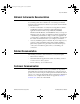
User.book Page 7 Tuesday, April 14, 1998 10:20 AM Chapter 6 Theory of Analog Operation versus sample rate is illustrated in Figure 6-3. For frequencies not near multiples of the oversample rate, the rejection is better than 85 dB. Alias Rejection (dB) 0.00 –10.00 –20.00 –30.00 –40.00 –50.00 –60.00 –70.00 –80.00 Sample Rate 1 kS/s Over-Sample 128 kHz Frequency 10 kS/s 100 kS/s 1 MS/s 1.28 MHz 12.8 MHz 128 MHz Figure 6-3.
User.book Page 8 Tuesday, April 14, 1998 10:20 AM Chapter 6 Theory of Analog Operation -0 -0 -20 -20 -40 -40 -60 -60 -80 -80 -100 -100 -120 -120 -140 0 5000 -140 10000 15000 20000 25000 a. Clipped Signal 0 5000 10000 15000 20000 25000 b. Proper Signal Figure 6-4. Comparison of a Clipped Signal to a Proper Signal An overrange can occur on the analog signal as well as on the digitized signal.
User.book Page 9 Tuesday, April 14, 1998 10:20 AM Chapter 6 Theory of Analog Operation The resulting output of the filter is a band-limited signal with a dynamic range of over 90 dB. One of the advantages of a delta-sigma ADC is that it uses a 1-bit DAC as an internal reference, whereas most 16-bit ADCs use 16-bit resistor-network DACs or capacitor-network DACs. As a result, the delta-sigma ADC is free from the kind of differential nonlinearity (DNL) that is inherent in most high-resolution ADCs.
User.book Page 10 Tuesday, April 14, 1998 10:20 AM Chapter 6 Theory of Analog Operation Analog Output Circuitry The PCI-4451 has two analog output channels, either of which is illustrated in Figure 4-4, Analog Output Channel Block Diagram. A common application for the analog output is to stimulate a system under test while measuring the response with the analog inputs. The input and output sample clocks are synchronized and derived from the same DDS clock.
User.book Page 11 Tuesday, April 14, 1998 10:20 AM Chapter 6 Theory of Analog Operation of eight times the sample rate, as shown in Figure 6-5c. Still, images remain and they must be filtered out. Each output channel of the PCI-4451 has discrete-time (switched-capacitor) and continuous-time analog filters that remove the high-frequency images, as shown in Figure 6-5d. Images Amplitude Baseband Signal Fs 16 Fs Frequency 16 Fs Frequency 8 Fs c.
User.book Page 12 Tuesday, April 14, 1998 10:20 AM Chapter 6 Theory of Analog Operation The DAC The 64-times oversampling delta-sigma DACs on the PCI-4451 work in the same way as delta-sigma ADCs, only in reverse. The digital data first passes through a digital lowpass filter and then goes to the delta-sigma modulator.
User.book Page 13 Tuesday, April 14, 1998 10:20 AM Chapter 6 Theory of Analog Operation Mute Feature The two-channel DAC chip on the PCI-4451 goes into mute mode if the chip receives at least 4,096 consecutive zero values on both channels at once. In mute mode, the outputs clamp to ground and the noise floor drops from about 92 dB below full-scale to about 120 dB below full-scale. Upon receiving any nonzero data, the DAC instantly reverts to normal mode.
User.book Page 1 Tuesday, April 14, 1998 10:20 AM A Specifications This appendix lists the specifications of the PCI-4451/4452. These specifications are typical at 25° C unless otherwise noted. The system must be allowed to warm-up for 15 minutes to achieve the rated accuracy. Note Be sure to keep the cover on your computer to maintain forced air cooling. Analog Input Channel Characteristics Number of channels ...............................
User.book Page 2 Tuesday, April 14, 1998 10:20 AM Appendix A Specifications Gain Linear Log Full-Scale Range (Peak) 31.6 +30 dB ±0.316 V 100 +40 dB ±0.100 V 316 +50 dB ±0.0316 V 1000 +60 dB ±0.0100 V FIFO buffer size......................................512 samples Data transfers ..........................................DMA, programmed I/O, interrupt Transfer Characteristics INL (relative accuracy)...........................±2 LSB DNL .....................................................
User.book Page 3 Tuesday, April 14, 1998 10:20 AM Appendix A Specifications Amplifier Characteristics Input impedance ..................................... 1 MΩ in parallel with 50 pF (+ and − each to AIGND) Frequency response Gain 0, +10, +20, +30, +40 dB................ ±0.1 dB, 0 to 95 kHz, 204.8 kS/s, DC coupling −20, −10, +50, +60 dB .................... ±1 dB, 0 to 95 kHz, ±0.1 dB, 0 to 20 kHz −3 dB bandwidth .................................... 0.493 fs Input coupling .............................
User.book Page 4 Tuesday, April 14, 1998 10:20 AM Appendix A Specifications Noise (dB Full-Scale) –65.0 Gain = +60 dB –70.0 –75.0 Gain = +50 dB –80.0 –85.0 Gain = +40 dB –90.0 –95.0 1,000 Gain = All Others 10,000 100,000 1,000,000 Sample Rate (S/s) Figure A-1. Idle Channel Noise (Typical) Input noise spectral density ....................8 nV/ Hz (achievable only at Gain = +50 dB or +60 dB) Dynamic Characteristics Alias-free bandwidth ..............................DC to 0.
User.book Page 5 Tuesday, April 14, 1998 10:20 AM Appendix A Specifications Phase linearity ........................................ ±1°, Gain ≥ 0 dB, ±2°, Gain < 0 dB Interchannel phase.................................. ±1°, Gain ≥ 0 dB, ±2°, Gain < 0 dB (same configuration all input channels) Interchannel gain mismatch ................... ±0.1dB, for all gains (same configuration for all input channels) Signal delay............................................
User.book Page 6 Tuesday, April 14, 1998 10:20 AM Appendix A Specifications Output signal range, software-selectable Attenuation Linear Log Full-scale Range 1 0 dB ±10.0 V 10 20 dB ±1.00 V 100 40 dB ±0.100 V FIFO buffer size......................................512 samples Data transfers ..........................................DMA, programmed I/O, Interrupt Transfer Characteristics Offset (residual DC) ...............................±5 mV max, any gain Gain (amplitude accuracy)............
User.book Page 7 Tuesday, April 14, 1998 10:20 AM Appendix A Specifications Dynamic Characteristics Image-free bandwidth ............................ DC to 0.450 fs Image rejection....................................... 90 dB, 0.550 fs < fout < 63.450 fs Spurious-free dynamic range ................. 90 dB, DC to 100 kHz THD ....................................................... −80 dB; −90 dB for fout < 5 kHz or signal < 1 Vrms IMD........................................................
User.book Page 8 Tuesday, April 14, 1998 10:20 AM Appendix A Specifications Digital logic levels Level Min Max Input low voltage 0.0 V 0.8 V Input high voltage 2.0 V 5.0 V Input low current (V = 0 V) — −320 µA Input high current (V = 5 V) — 10 µA Output low voltage (I — 0.4 V 4.35 V — in in OL Output high voltage (I = 24 mA) OH = 13 mA) Power-on state ........................................Input (High-Z) Data transfers ..........................................
User.book Page 9 Tuesday, April 14, 1998 10:20 AM Appendix A Specifications DMA modes ........................................... Scatter gather Triggers Analog Trigger Source PCI-4451 ......................................... ACH<0..1> PCI-4452 ......................................... ACH<0..3> Level....................................................... ± full-scale Slope....................................................... Positive or negative (software selectable) Resolution .....................
User.book Page 10 Tuesday, April 14, 1998 10:20 AM Appendix A Specifications Available power......................................+4.65 to +5.25 VDC at 0.5 A (analog I/O connector) Available power......................................+4.65 to +5.25 VDC at 1.0 A (digital I/O connector) Physical Dimensions (not including connectors) ..10.65 by 31.19 by 1.84 cm (4.19 by 12.28 by 0.73 in.) Digital I/O connector ..............................50-pin VHDIC female type Analog I/O connector .....................
User.book Page 1 Tuesday, April 14, 1998 10:20 AM B Pin Connections This appendix describes the pin connections on the optional 68-pin digital accessories for the PCI-4451 and PCI-4452 devices.
User.
User.book Page 1 Tuesday, April 14, 1998 10:20 AM Customer Communication C For your convenience, this appendix contains forms to help you gather the information necessary to help us solve your technical problems and a form you can use to comment on the product documentation. When you contact us, we need the information on the Technical Support Form and the configuration form, if your manual contains one, about your system configuration to answer your questions as quickly as possible.
User.book Page 2 Tuesday, April 14, 1998 10:20 AM Fax-on-Demand Support Fax-on-Demand is a 24-hour information retrieval system containing a library of documents on a wide range of technical information. You can access Fax-on-Demand from a touch-tone telephone at 512 418 1111. E-Mail Support (Currently USA Only) You can submit technical support questions to the applications engineering team through e-mail at the Internet address listed below.
User.book Page 3 Tuesday, April 14, 1998 10:20 AM Technical Support Form Photocopy this form and update it each time you make changes to your software or hardware, and use the completed copy of this form as a reference for your current configuration. Completing this form accurately before contacting National Instruments for technical support helps our applications engineers answer your questions more efficiently.
User.book Page 5 Tuesday, April 14, 1998 10:20 AM PCI-4451/4452 Hardware and Software Configuration Form Record the settings and revisions of your hardware and software on the line to the right of each item. Complete a new copy of this form each time you revise your software or hardware configuration, and use this form as a reference for your current configuration.
User.book Page 7 Tuesday, April 14, 1998 10:20 AM Documentation Comment Form National Instruments encourages you to comment on the documentation supplied with our products. This information helps us provide quality products to meet your needs. Title: PCI-4451/4452 User Manual Edition Date: April 1998 Part Number: 321891A-01 Please comment on the completeness, clarity, and organization of the manual.
User.
User.book Page 2 Tuesday, April 14, 1998 10:20 AM Glossary ADC analog-to-digital converter—an electronic device, often an integrated circuit, that converts an analog voltage to a digital number ADC resolution the size of the discrete steps in the ADC’s input-to-output transfer function; therefore, the smallest voltage difference an ADC can discriminate with a single measurement AI Convert LabVIEW name for CONVERT*. See CONVERT* AI Start Trigger LabVIEW name for TRIG1.
User.book Page 3 Tuesday, April 14, 1998 10:20 AM Glossary B b bit—one binary digit, either 0 or 1 B byte—eight related bits of data, an eight-bit binary number. Also used to denote the amount of memory required to store one byte of data bandwidth the range of frequencies present in a signal, or the range of frequencies to which a measuring device can respond base address a memory address that serves as the starting address for programmable registers.
User.
User.
User.book Page 6 Tuesday, April 14, 1998 10:20 AM Glossary delta-sigma modulating ADC a high-accuracy circuit that samples at a higher rate and lower resolution than is needed and (by means of feedback loops) pushes the quantization noise above the frequency range of interest. This out-of-band noise is typically removed by digital filters. device a plug-in data acquisition board, card, or pad that can contain multiple channels and conversion devices.
User.book Page 7 Tuesday, April 14, 1998 10:20 AM Glossary E EEPROM electrically erasable programmable read-only memory—ROM that can be erased with an electrical signal and reprogrammed EMC electromechanical compliance encoder a device that converts linear or rotary displacement into digital or pulse signals. The most popular type of encoder is the optical encoder, which uses a rotating disk with alternating opaque areas, a light source, and a photodetector.
User.book Page 8 Tuesday, April 14, 1998 10:20 AM Glossary filtering a type of signal conditioning that allows you to attenuate unwanted portions of the signal you are trying to measure FIR finite impulse response—a non recursive digital filter with linear phase flash ADC an ADC whose output code is determined in a single step by a bank of comparators and encoding logic floating signal sources signal sources with voltage signals that are not connected to an absolute reference or system ground.
User.book Page 9 Tuesday, April 14, 1998 10:20 AM Glossary H h hour half-power bandwidth the frequency range over which a circuit maintains a level of at least –3 dB with respect to the nominal level handshaked digital I/O a type of digital acquisition/generation where a device or module accepts or transfers data after a digital pulse has been received. Also called latched digital I/O.
User.book Page 10 Tuesday, April 14, 1998 10:20 AM Glossary input impedance the measured resistance and capacitance between the input terminals of a circuit input offset current the difference in the input bias currents of the two inputs of an instrumentation amplifier instrument driver a set of high-level software functions that controls a specific GPIB, VXI, or RS-232 programmable instrument or a specific plug-in DAQ board.
User.
User.book Page 12 Tuesday, April 14, 1998 10:20 AM Glossary M m meters M (1) Mega, the standard metric prefix for 1 million or 106, when used with units of measure such as volts and hertz; (2) mega, the prefix for 1,048,576, or 220, when used with B to quantify data or computer memory Mbytes/s a unit for data transfer that means 1,048,576 bytes/s memory buffer See buffer. MITE MXI Interface to Everything—a custom ASIC designed by National Instruments that implements the PCI bus interface.
User.book Page 13 Tuesday, April 14, 1998 10:20 AM Glossary nonreferenced signal sources signal sources with voltage signals that are not connected to an absolute reference or system ground. Also called floating signal sources. Some common example of nonreferenced signal sources are batteries, transformers, or thermocouples.
User.
User.book Page 15 Tuesday, April 14, 1998 10:20 AM Glossary R real time a property of an event or system in which data is processed as it is acquired instead of being accumulated and processed at a later time relative accuracy a measure in LSB of the linearity of an ADC. It includes all non-linearity and quantization errors. It does not include offset and gain errors of the circuitry feeding the ADC. resolution the smallest signal increment that can be detected by a measurement system.
User.book Page 16 Tuesday, April 14, 1998 10:20 AM Glossary sample counter the clock that counts the output of the channel clock, in other words, the number of samples taken. On boards with simultaneous sampling, this counter counts the output of the scan clock and hence the number of scans.
User.
User.book Page 18 Tuesday, April 14, 1998 10:20 AM Glossary trigger any event that causes or starts some form of data capture TTL transistor-transistor logic U unipolar a signal range that is always positive (for example, 0 to +10 V) update the output equivalent of a scan. One or more analog or digital output samples. Typically, the number of output samples in an update is equal to the number of channels in the output group.
User.book Page 19 Tuesday, April 14, 1998 10:20 AM Glossary W waveform multiple voltage readings taken at a specific sampling rate WFTRIG word the standard number of bits that a processor or memory manipulates at one time. Microprocessors typically use 8-, 16-, or 32-bit words. working voltage the highest voltage that should be applied to a product in normal use, normally well under the breakdown voltage for safety margin.
User.
User.
User.
User.
User.
User.book Page 6 Tuesday, April 14, 1998 10:20 AM Index actual range and measurement precision, 3-6 posttriggered data acquisition, 4-15 power connections analog power connections, 4-12 digital power connections, 4-14 power requirement specifications, A-9 to A-10 pretriggered data acquisition, 4-16 programmable function inputs (PFIs). See PFIs (programmable function inputs).
User.
User.